
Synthesized resonation for an EL driver circuit

Active Publication Date: 2007-10-09
NAT SEMICON CORP
View PDF6 Cites 13 Cited by
  • Summary
  • Abstract
  • Description
  • Claims
  • Application Information

AI Technical Summary

Problems solved by technology

However, inductor based driver circuits can produce relatively large amounts of electromagnetic interference (EMI), which is known to adversely effect the operation of many electronic components.

Method used


Image

  • Synthesized resonation for an EL driver circuit
  • Synthesized resonation for an EL driver circuit
  • Synthesized resonation for an EL driver circuit

Examples


Embodiment Construction

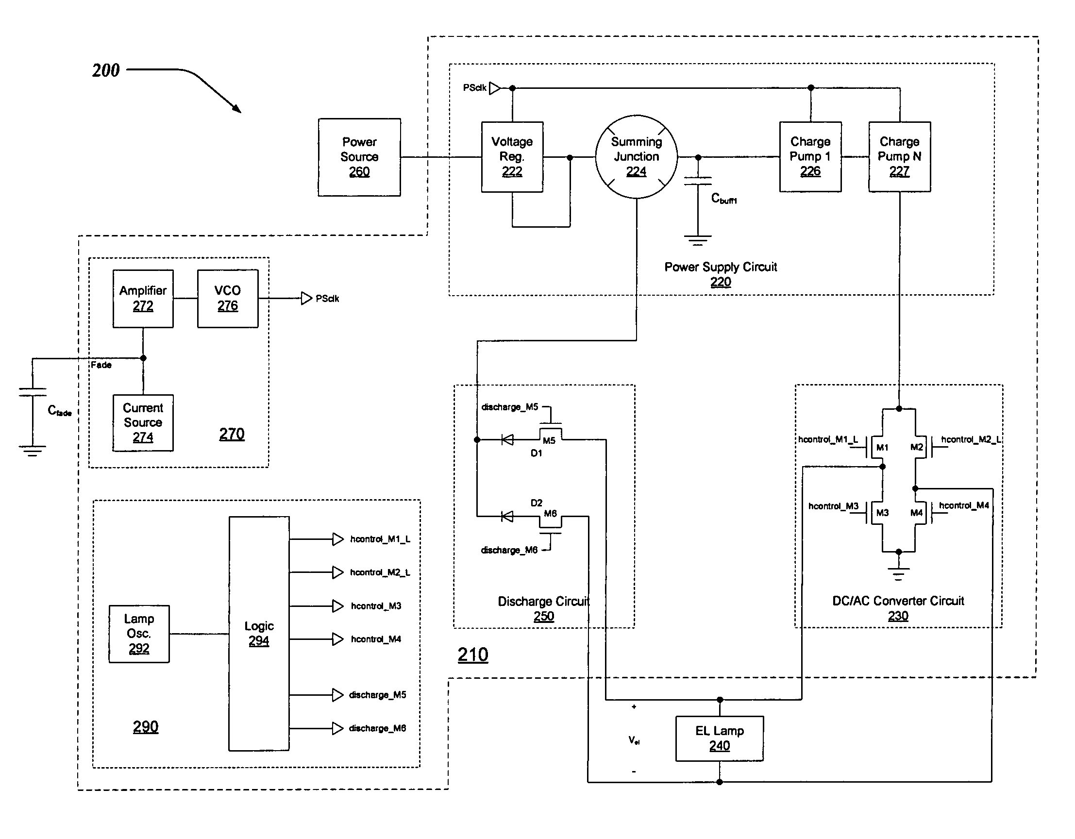
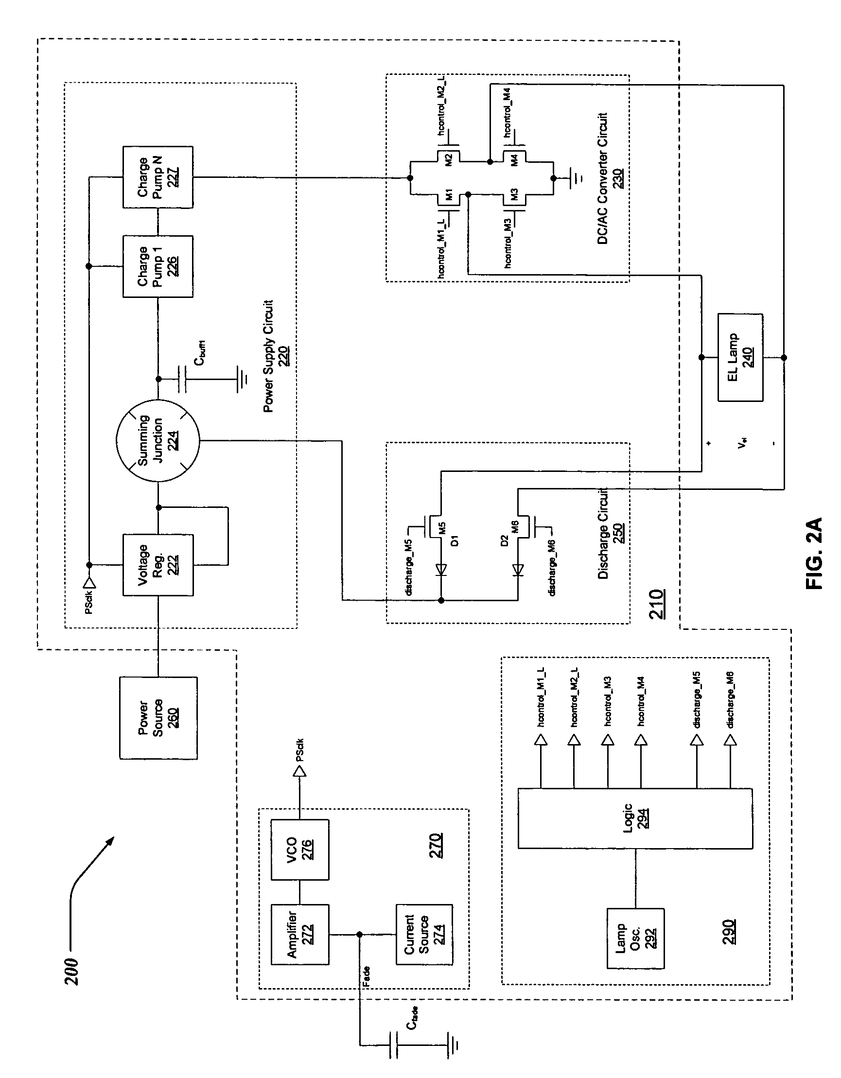
[0013]Throughout the specification and claims, the following terms take at least the meanings explicitly associated herein, unless the context dictates otherwise. The meanings identified below do not necessarily limit the terms, but merely provide illustrative examples for the terms. The meaning of “a,”“an,” and “the” includes plural reference, and the meaning of “in” includes “in” and “on.” The phrase “in one embodiment,” as used herein does not necessarily refer to the same embodiment, although it may. The term “coupled” means at least either a direct electrical connection between the items connected, or an indirect connection through one or more passive or active intermediary devices such as resistor, capacitor, diode, transistor, relay, switch, integrated circuit, and / or the like. The term “circuit” means at least either a single component or a multiplicity of components, either active and / or passive, that are coupled together to provide a desired function. The term “signal” mea...


PUM


Abstract

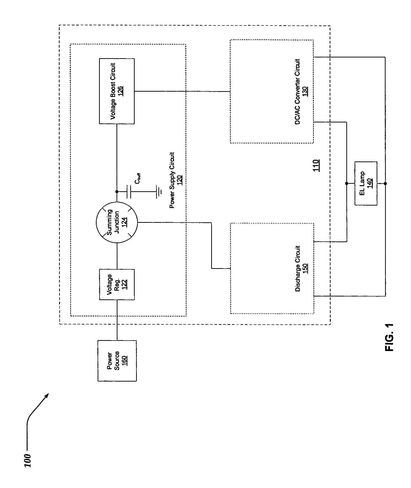
A driver circuit for an electroluminescent (EL) lamp that consumes less power and reduces electromagnetic interference (EMI). Electrical charge is stored during a discharge cycle of an AC signal employed to illuminate an EL lamp, and subsequently reused during the AC signal's charging cycle. The reuse of electrical charge enables the driver circuitry to illuminate the EL lamp while drawing the least amount of power from a power supply, such as a battery. Also, multiple charge pumps can be sequentially / serially turned off during the discharge cycles of the AC signal driving the EL Lamp. By sequentially discharging the EL lamp, a waveform for the AC signal can be synthesized that more closely resembles a relatively symmetrical sinusoidal shape. The relatively symmetrical shape of the synthesized AC waveform serves at least in part to reduce spurious emissions of electromagnetic interference (EMI), audio noise, and improve the efficiency of the driver circuitry.

Description

FIELD OF THE INVENTION[0001]The invention relates to supplying power to a lamp, and more particularly, to conserving electrical charge from a battery that is used to power an electroluminescent (EL) lamp.BACKGROUND OF THE INVENTION[0002]EL lamps are commonly used to illuminate the controls and / or displays of many electronic devices. A typical EL lamp is a capacitive element which illuminates when driven by an alternating current (AC) of proper magnitude and frequency.[0003]A typical EL lamp driver circuit generates a peak-to-peak voltage AC waveform of 100 Volts or more with a frequency of a few hundred Hertz to enable an EL lamp to produce sufficient illumination. Specialized inductor based driver circuitry is often used to generate this AC waveform from a direct current (DC) source, such as a battery. However, inductor based driver circuits can produce relatively large amounts of electromagnetic interference (EMI), which is known to adversely effect the operation of many electroni...

Claims


Application Information

Patent Timeline
IPC IPC(8): G05F1/10G05F1/00
CPCH05B33/08Y02B20/325Y02B20/30H05B44/00
Inventor MULLIN, JEFFREY DOYLEYIN, YAN
Owner NAT SEMICON CORP
Learn More