Display method, display apparatus and data write circuit utilized therefor

a display method and data write circuit technology, applied in the field of display technologies, can solve the problems of lcds and pdps, subject to some degradation of moving picture quality, etc., and achieve the effect of improving the visibility of moving images and improving the quality of moving pictures

Active Publication Date: 2007-10-09
SANYO ELECTRIC CO LTD
View PDF13 Cites 47 Cited by
  • Summary
  • Abstract
  • Description
  • Claims
  • Application Information

AI Technical Summary

Benefits of technology

[0009]The present invention has been made to eliminate the above-mentioned blur effect and an object thereof is to provide a hold-type display with improved moving picture quality or improved visibility of moving images. Another object thereof is to provide a technology that is applicable also to the type of displays, such as PDP, which are self-luminous without light sources.
[0010]A preferred embodiment according to the present invention relates to a display method. This method is characterized in that effective writing is conducted in a concentrated manner in a partial period during a frame period when a desired pixel value is written to a pixel in a hold-type display apparatus and, in so conducting, a write value in the partial period is set higher than the desired pixel value so that the desired pixel value is realized, in terms of visibility, by the writing in the partial period “The desired pixel value is realized in terms of visibility” means, for example, that desired brightness is realized. According to this method, write values to be written to pixels are relatively low except for the partial period, with the result that the satisfactory visibility of moving images similar to that realized in the impulse-type display apparatus can be obtained.
[0012]Examples for the predetermined relationship include a case that the both values are equal, a case that one is proportional to the other and vice versa, a case that one is a function of the other and so forth. If the both values are equal, the display brightness for both the commonly used conventional display method and the method according to the present embodiment is equal to each other. According to the present method, the write values to be written to the pixels become small except for the partial period, so that the visibility of moving images is improved. If the former is larger, brighter images will of course be obtained. If, on the other hand, the latter is larger, the visibility of moving images will be further improved.
[0015]Still another preferred embodiment according to the present invention relates also to a data write circuit for driving a hold-type display apparatus. This data write circuit includes means for writing in a first period n times a desired pixel value to be written to a pixel and writing 0 (zero) in a second period and thereafter where a frame period is divided into n parts and each divided period is denoted by first to nth period (n being an integer greater than or equal to 2). However, when a pixel value that is n times the desired pixel value exceeds a displayable range of the display apparatus, the writing means writes to the pixel an upper limit value of the range in the first period, and an excess part that remains unwritten is written to the pixel upon arrival of the second period and, thereafter, an excess part that cannot be written out in an ith period (2≦i≦n−1) is written sequentially upon arrival of an (i+1)th period. In this manner, the effective writing can be completed at as early timing as possible, so that the visibility of moving images can be improved.
[0017]In such a case, the writing of the pixel value can be concentrated in a partial period during a frame period, so that the visibility of moving images can be improved. For example, when the color of a pixel consists in a plurality thereof such as RGB, the ith period serves as the temporal center at the time of writing a pixel value in any of colors Thus, the maximum timings of brightness are synchronized among pixels of different colors and, as a result thereof, the deterioration of the visibility due to the so-called color distortion can be easily prevented.

Problems solved by technology

However, it is now known that LCDs and PDPs (hereinafter referred to as “LCDs and the like”) are subject to some degradation of moving picture quality due to a difference in display principle from CRTs.
As a result, for the eyes that follow the moving object in a smooth motion, there results a disparity between the position of the displayed moving object and the position sensed by the eyes as the center of the moving object, so that the moving object is recognized as a blurred image.

Method used


Image

  • Display method, display apparatus and data write circuit utilized therefor
  • Display method, display apparatus and data write circuit utilized therefor
  • Display method, display apparatus and data write circuit utilized therefor

Examples


Embodiment Construction

[0036]The invention will now be described based on the following embodiments which do not intend to limit the scope of the present invention but exemplify the invention. All of the features and the combinations thereof described in the embodiments are not necessarily essential to the invention.

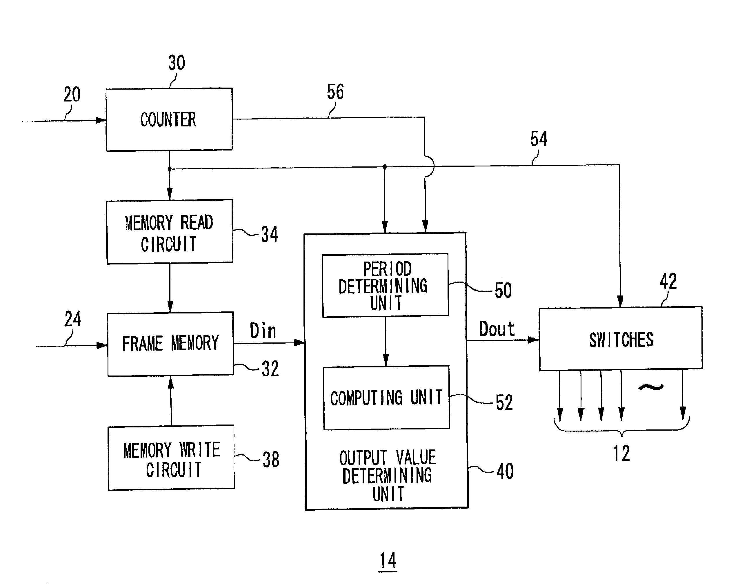
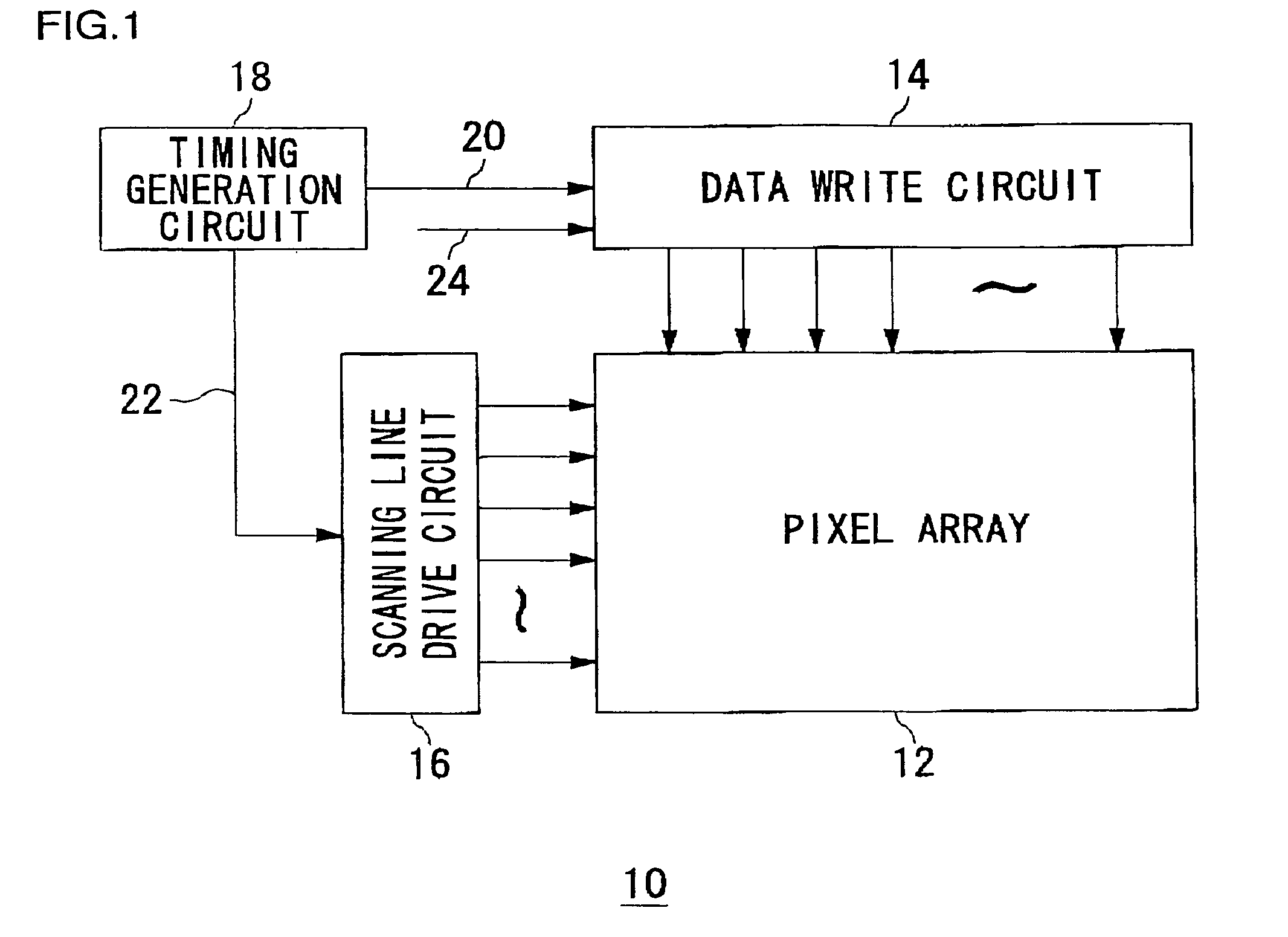
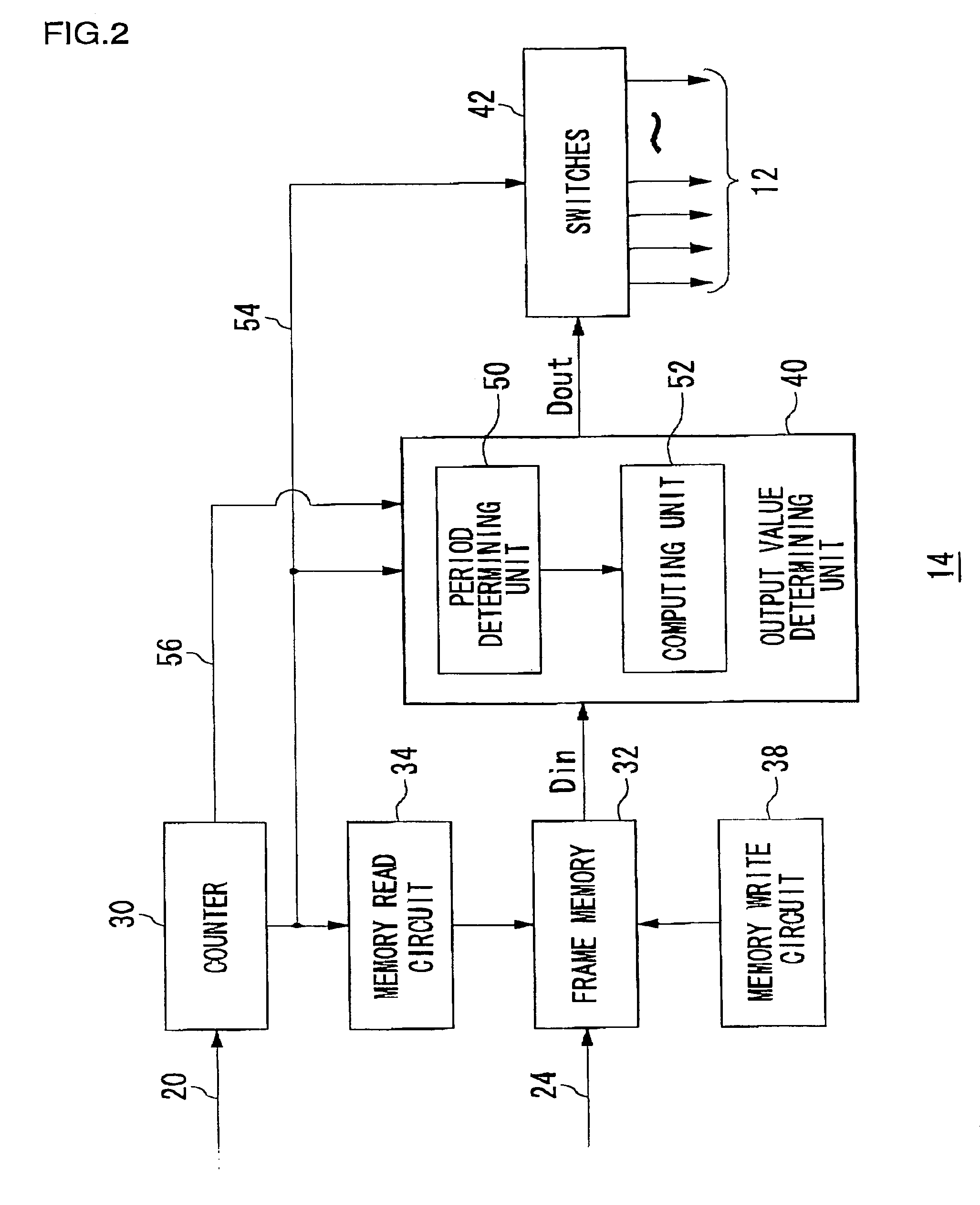
[0037]FIG. 1 shows a structure of a display apparatus 10 according to an embodiment of the present invention. The display apparatus 10 includes a pixel array 12 comprised of liquid crystals arranged in a matrix, a data write circuit 14 for writing pixel values, or pixel data, to the pixels in each row of the pixel array 12, a scanning line drive circuit 16 for scanning the pixel array 12 in the column direction, and a timing generation circuit 18 for setting timings for the write operation by the data write circuit 14 and the scanning line drive circuit 16.

[0038]The timing generation circuit 18, which has a built-in PLL (Phase Lock Loop) circuit, generates for the data write circuit 14 the num...


PUM

PropertyMeasurementUnit
frequencyaaaaaaaaaa
speedaaaaaaaaaa
brightnessaaaaaaaaaa

Abstract

A hold-type display apparatus is more likely to suffer the deterioration in the visibility of moving images due to the blur effect, compared to an impulse-type display apparatus. A single frame period is divided into a first period and a second period. Pixel data to be written to a pixel are written in a concentrated manner in the first period during a frame period. At this time, a write value for the pixel is set to twice a value of the image data in order not to lower the brightness of the images as a whole. However, only if the doubled value exceeds a range that can be displayed, the remaining pixel data are written in the second period. Thus, the change in display brightness approximates the impulse-type display apparatus, so that the visibility of moving images is improved.

Description

BACKGROUND OF THE INVENTION[0001]1. Field of the Invention[0002]The present invention relates to the display technologies, and it particularly relates to a method for displaying the moving pictures on a hold-type display apparatus, a display apparatus utilizing said method and a data write circuit usable for said display apparatus.[0003]2. Description of the Related Art[0004]Liquid crystal displays (hereinafter referred to as “LCDs”) and plasma displays (hereinafter referred to as “PDPs”) are increasingly becoming high-performance in recent years. These displays, helped by their intrinsically thin structure, are now about to wrest the leading role for TV receivers from cathode-ray tubes (hereinafter referred to as “CRTs”). This trend may keep accelerating in the years ahead.[0005]However, it is now known that LCDs and PDPs (hereinafter referred to as “LCDs and the like”) are subject to some degradation of moving picture quality due to a difference in display principle from CRTs. Tha...

Claims


Application Information

Patent Timeline
Patent Type & Authority Patents(United States)
IPC IPC(8): G09G3/36G02F1/133G09F9/00G09G3/20H04N5/66
CPCG09G3/20G09G3/2022G09G3/2081G09G3/2003G09G2320/106G09G3/3607G09G3/3611G09G2310/08G09G2320/0261G09G3/28
Inventor TAOKA, MINEKIMORI, YUKIOIKEDA, TAKASHI
Owner SANYO ELECTRIC CO LTD
Why Eureka
Try Eureka