Accurate determination of refractive indices of solid, fluid and liquid materials

a technology of refractive index and solid, fluid and liquid materials, applied in the direction of phase-affecting property measurement, instruments, measurement devices, etc., can solve the problem of entering errors into accurate determination of refractive index of a material, and achieve the effect of effective repeating, and improving accuracy in determining refractive index

Active Publication Date: 2007-10-09
J A WOOLLAM CO
View PDF14 Cites 12 Cited by
  • Summary
  • Abstract
  • Description
  • Claims
  • Application Information

AI Technical Summary

Benefits of technology

[0061]Another step, in the case where a System identified in 2 or 4 above is utilized and liquid / fluid is investigated, can involve effectively repeating the method without the liquid / fluid present inside the cavity and with the prism oriented to allow electromagnetic radiation to pass straight-through, to determine base line effects of the Prism System. This allows determination of any non-parallelism effects of the Windows. Said baseline effects can then be subtracted from the data obtained when liquid / fluid is present to further improve accuracy in determining Refractive index.
[0062]Another step, in the case where a System identified as System 2 or 4 above is utilized and liquid / fluid is investigated, can involve effectively repeating the method with a standard liquid / fluid present inside the cavity to determine base line effects of the Prism System. Comparison with published data for said standard liquid / fluid can identify effects which can then be subtracted from the data obtained when sample liquid / fluid is present, to further improve accuracy in determining Refractive index. Measurements using the standard liquid / fluid can also help determine when proper alignment of the prism has been achieved, with said proper alignment then being utilized when measuring sample liquid / fluid.
[0092]Another step, in the case where a System identified as System 2, 4, 5, 6, 7 or 8 above is utilized and liquid / fluid is investigated can involve effectively repeating the method without the liquid / fluid present inside the cavity and with the prism oriented to allow electromagnetic radiation to pass straight-through, to determine base line effects of the Prism System. This allows determination of any non-parallelism effects of the Windows. Said baseline effects can then be subtracted from the data obtained when liquid / fluid is present to further improve accuracy in determining Refractive index.
[0093]Another step, in the case where a System identified as System 2, 4, 5, 6, 7 or 8 above is utilized and liquid / fluid is investigated, can involve effectively repeating the method with a standard liquid / fluid present inside the cavity to determine base line effects of the Prism System. Comparison with published data for said standard liquid / fluid can identify effects which can then be subtracted from the data obtained when sample liquid / fluid is present, to further improve accuracy in determining Refractive index. Measurements using the standard liquid / fluid can also help determine when proper alignment of the prism has been achieved, with said proper alignment then being utilized when measuring sample liquid / fluid.

Problems solved by technology

However, since it is impractical to direct the electromagnetic beam at said Apex, (especially where liquid is to be contained within a cavity in the Triangular shape prism), and as the electromagnetic beam is typically caused to impinge on the triangular shaped prism at a location removed therefrom, said measured / observed Minimum is not a True Minimum Deviation.
This can also enter error into accurate determination of Refractive Index of a material.

Method used


Image

  • Accurate determination of refractive indices of solid, fluid and liquid materials
  • Accurate determination of refractive indices of solid, fluid and liquid materials
  • Accurate determination of refractive indices of solid, fluid and liquid materials

Examples


Embodiment Construction

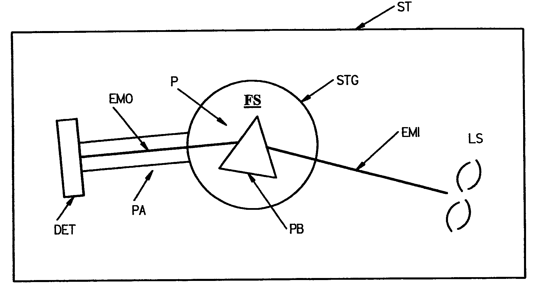
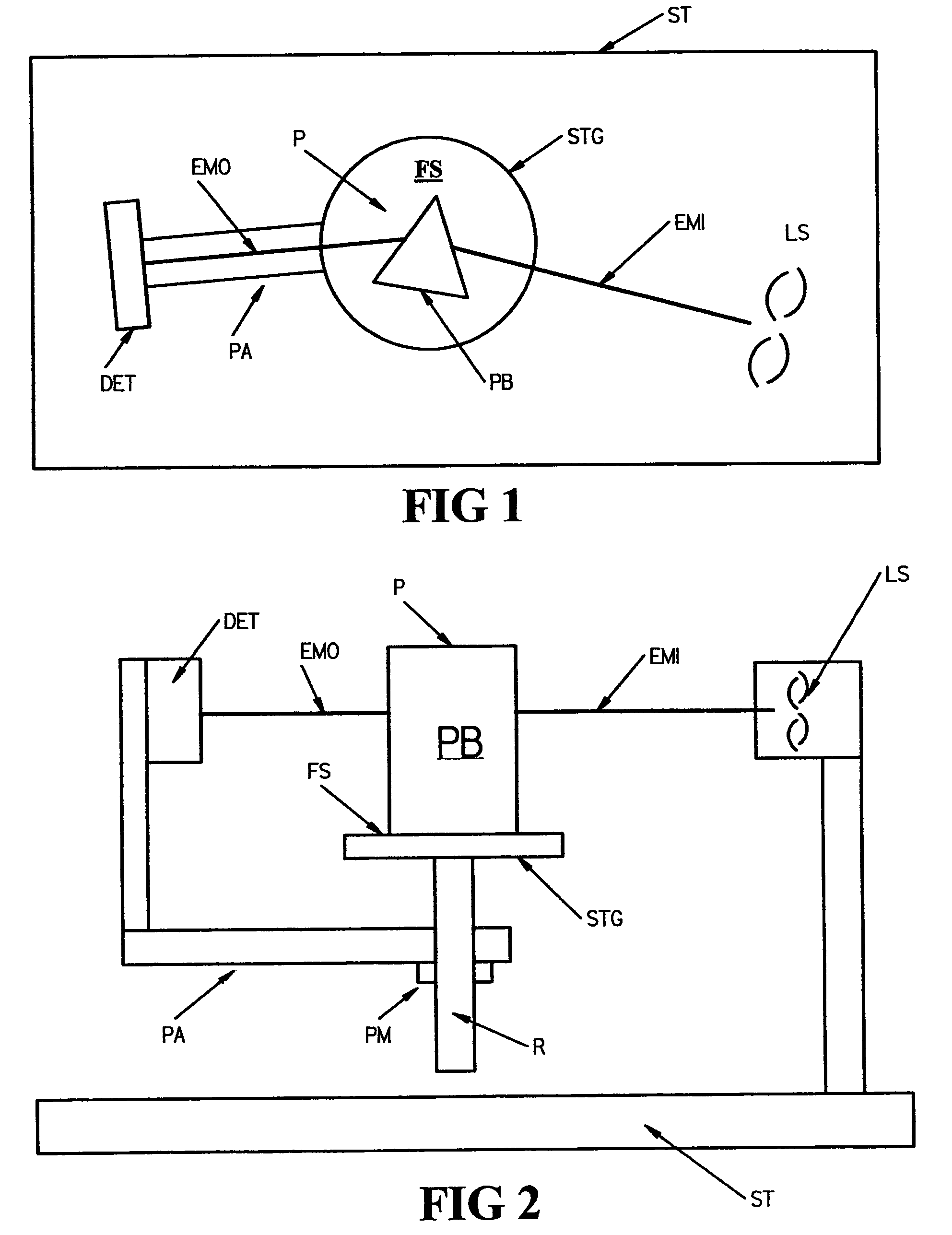
[0112]Turning now to the Drawings, there is shown in FIGS. 1 and 2, a System suitable for practicing the disclosed invention. Shown are a structure (ST), a source of electromagnetic radiation (LS), a stage (STG), and a detector (DET). Said stage is shown to have a front side (FS) which is defining of a stage plane, said source of electromagnetic radiation (LS) is fixed in location at an offset from said stage (STG). Said detector (DET) is attached to an arm (PA) which is pivotally secured to said structure (ST) the location of said stage (STG). Note that the relative positioning of said source of electromagnetic radiation (LS), stage (STG) and detector (DET) is such that a beam of electromagnetic radiation (EMI) produced by said source (LS) thereof can be directed to proceed in a plane parallel to, but offset from, the stage plane, and enter said detector (DET) when it is positioned at a detector pivot angle which allows receipt of said beam of electromagnetic radiation, said pivot ...


PUM

PropertyMeasurementUnit
Refractive Indexaaaaaaaaaa
refractive indexaaaaaaaaaa
electromagnetic radiationaaaaaaaaaa

Abstract

Systems and methodology for determining not only precise and repeatable results, but accurate values of the refractive index of solids, fluids and liquids.

Description

TECHNICAL FIELD[0001]The disclosed invention relates to determination of refractive indices of materials, and more particularly to systems and methodology for determining not only precise and repeatable results, but accurate values of the refractive index of solids, fluids and liquids.BACKGROUND[0002]As semiconductor device dimensions decrease, the need to perform lithography at shorter wavelengths becomes more critical. One method of simulating the results achievable by direct application of short wavelengths, is to apply longer wavelengths through refractive liquid. Accurate determination of the refractive index of liquids to be applied in said simulated shorter wavelength lithography then becomes critical.[0003]A well known technique for determining the refractive index of a material is to provide a triangular shaped prism of the material, mount it to a front of a rotatable stage, provide a beam of electromagnetic radiation which is directed to impinge upon one side thereof, and ...

Claims


Application Information

Patent Timeline
Patent Type & Authority Patents(United States)
IPC IPC(8): G01N21/41
CPCG01N21/4133
Inventor HERZINGER, CRAIG M.GREEN, STEVEN E.PRIBIL, GREGORY K.
Owner J A WOOLLAM CO
Why Eureka
Try Eureka