Arrangement for supplying fuel to the fuel injectors of an internal combustion engine

a technology for injectors and internal combustion engines, which is applied in the direction of fuel injection apparatus, machine/engines, feed systems, etc., can solve the problems of limited performance of high-pressure electrical pumps, and achieve the effect of accurately adjusting the pressure level and increasing the pressure level

Active Publication Date: 2007-10-16
DAIMLER AG
View PDF13 Cites 24 Cited by
  • Summary
  • Abstract
  • Description
  • Claims
  • Application Information

AI Technical Summary

Benefits of technology

[0010]In one embodiment, the fuel supply arrangement includes a low pressure fuel pump with a high pressure pump arranged in series therewith which can selectively be switched on for increasing the fuel injection pressure. In a section of the high pressure line downstream of the high pressure pump a relief line is connected to the pressure line and is connected at its other end to a low pressure section of the fuel line upstream of the high pressure pump. The relief line includes a switchable relief valve structure so that, by closing the relief valve, the pressure level is increased by activating the high pressure pump. In this way, with simple means, an arrangement is provided in which, with a simple valve structure, the high pressure pump can be switched in and by opening the valve structure the low pressure level of the upstream fuel pump can be provided. The valve structure may be a magnetic valve, which, under normal operation is de-energized, that is open and, for activating the high pressure pump for increasing the fuel pressure, is closed. Expediently, the high pressure pump is operated electrically and therefore can immediately provide the high fuel pressure level in the pressure line of the injectors upon start-up of the engine.
[0012]In an alternative embodiment of the fuel supply arrangement, a pressure storage device may be provided so as to be connectable, by way of a connecting line with a valve, to the suction side of the fuel pump in the fuel supply line upstream of the fuel pump, whereby, with an opening of the connecting line, an increased pressure level can be instantly established. Such a fuel supply arrangement may be quite compact by supplying fuel to the pressurized fuel storage device from a fuel supply line which is connected to the fuel pressure line downstream of a pressure control device arranged in the pressure line. The relief line of the pressure controller which is adapted to the low pressure level is closed, whereby the fuel pump generates a pressure level beyond normal pressure when the engine consumes a relatively small amount of fuel. For controlling the injection pressure in the operating phase with an increased injection pressure in the operating phase an advance control by a variable throttle in the connecting line of the pressure storage device is expedient.
[0013]The pressure storage device can preferably be controlled by means of a control unit which also controls the injectors, the control unit being in communication with pressure sensors at the pressure storage device and in the pressure line. With a possible drop of the preliminary pressure of the pressure storage device or, respectively, a drop of the high pressure to the low normal pressure, the injection times of the injectors are adapted to the available injection pressure for an optimal injection result using stored performance graph data. In a preferred embodiment of the invention, a controllable fuel pump is provided which is controlled by the control unit taking into consideration the pressure available from the pressure storage device, so that the fuel injection process can be accurately adjusted.

Problems solved by technology

With this arrangement, only a limited performance for this high pressure electrical pump is required to obtain a sufficiently high fuel pressure for a good atomization of the fuel in the combustion chamber.

Method used


Image

  • Arrangement for supplying fuel to the fuel injectors of an internal combustion engine
  • Arrangement for supplying fuel to the fuel injectors of an internal combustion engine
  • Arrangement for supplying fuel to the fuel injectors of an internal combustion engine

Examples


Embodiment Construction

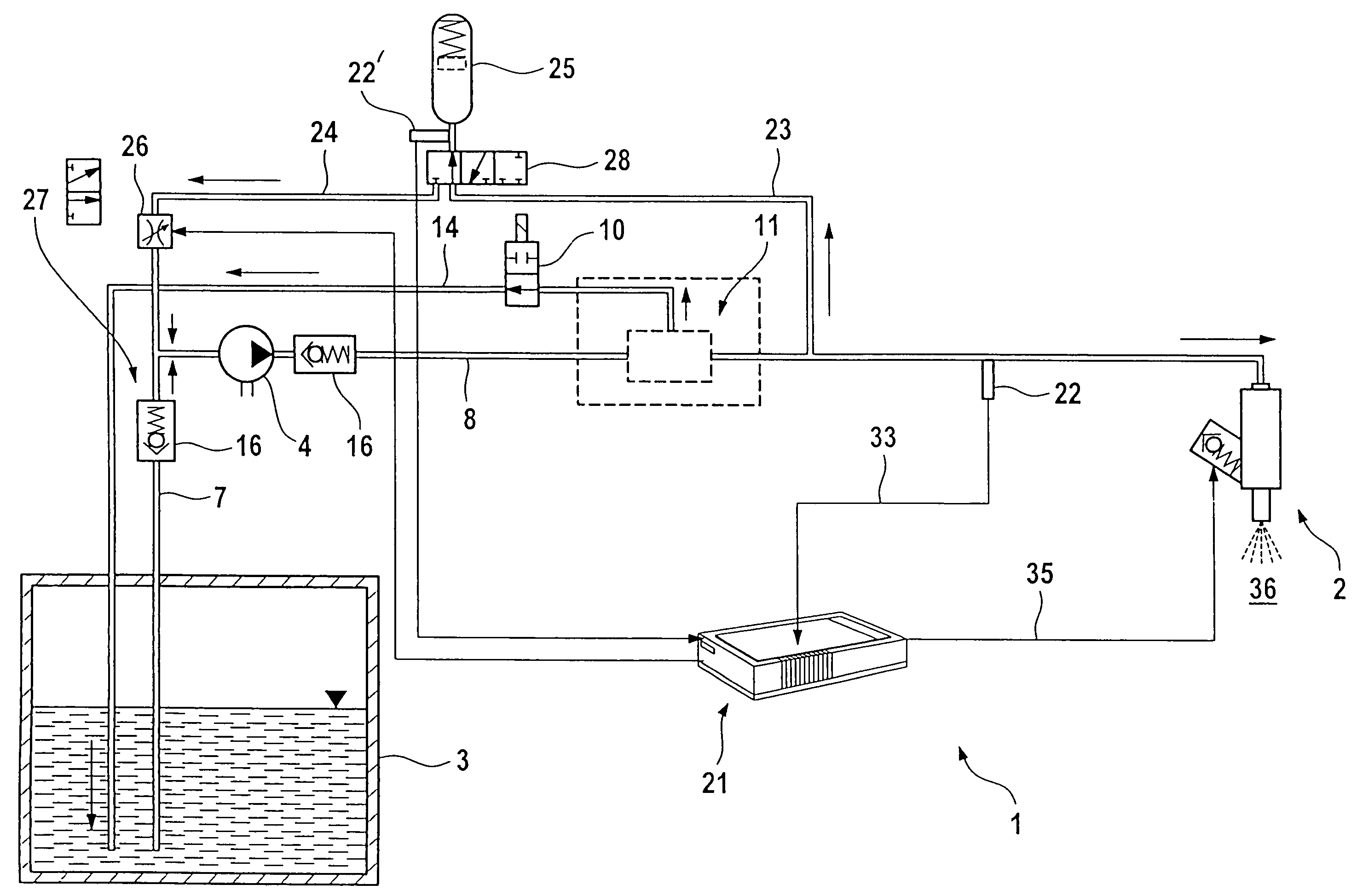
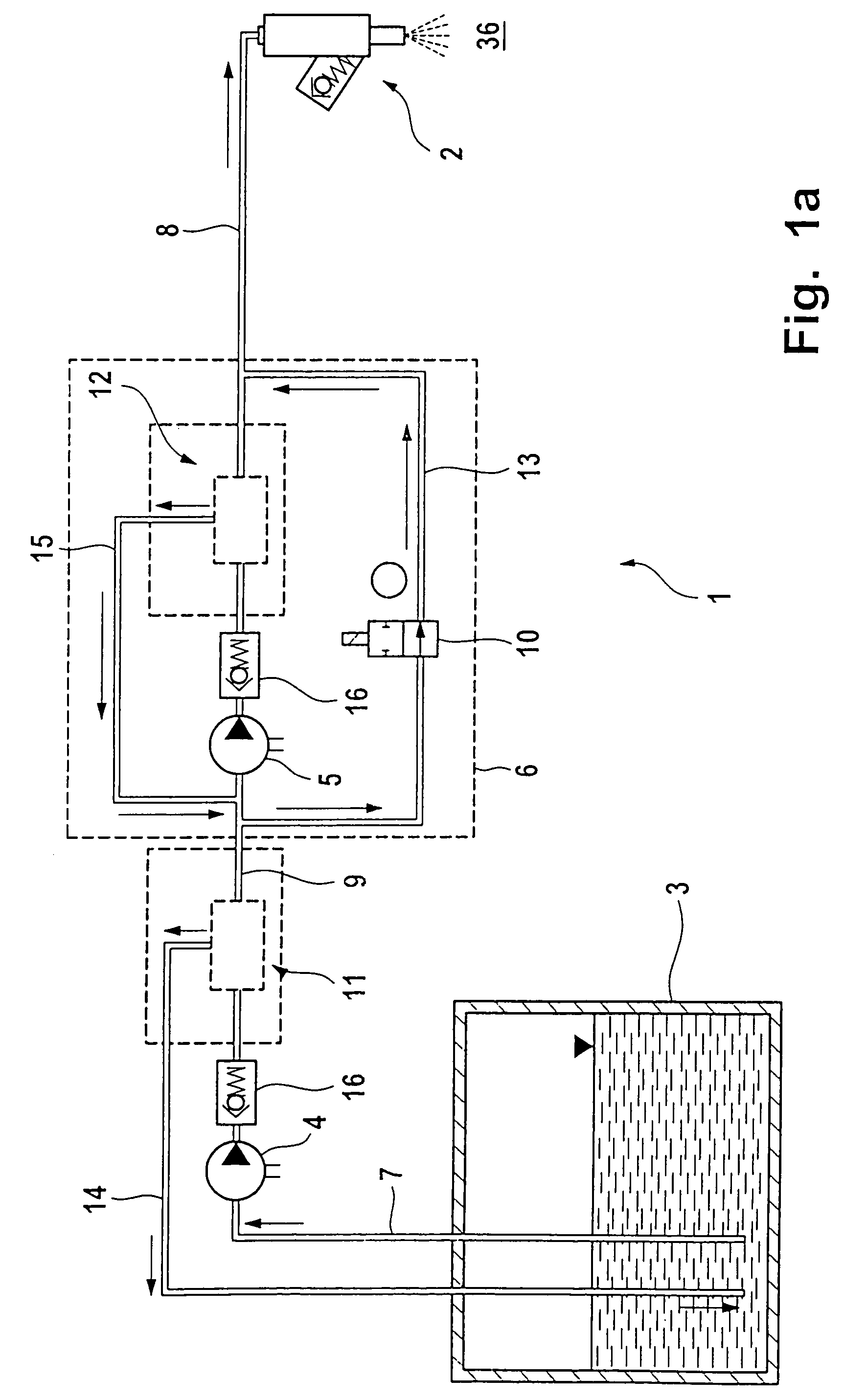
[0021]FIGS. 1a-1c show a fuel supply arrangement 1 for supplying fuel to the injectors 2 extending into the combustion chamber 36 of an internal combustion engine. The fuel supply arrangement 1 comprises a pumping device which, by way of a supply line 7, provides fuel from a fuel tank 3 to a pressure line 8 under a certain pressure for the injection of the fuel into the combustion chamber. The pressure line 8 is connected to injectors 2 for supplying the fuel thereto, wherein the end of the pressure line 8 is in the form of a common rail via which all the injectors 2 are supplied with fuel. The pump arrangement comprises an electric fuel pump 4 whose input is connected to the supply line 7 extending from the fuel tank 3. The fuel pump 4 is designed for an injection pressure as needed for normal engine operation which in the present embodiment is 3.8 bar. The pumping arrangement furthermore includes a device 6 for increasing the pressure which is connectable for increasing the operat...


PUM


Abstract

In a fuel supply arrangement for supplying fuel from a fuel tank to the fuel injectors of an internal combustion engine by an electrically operated fuel pump, a first fuel pressure level adequate for normal engine operation is provided by the fuel pump and means are provided for increasing the fuel injection pressure provided by the pump for supplying fuel at a higher pressure level to the fuel injectors during an engine start-up or warm-up phase.

Description

BACKGROUND OF THE INVENTION[0001]The invention relates to an arrangement for supplying fuel to the fuel injectors mounted onto the cylinder heads of an internal combustion engine wherein fuel is supplied to the injectors by a pumping device through a pressure line under a static pressure.[0002]Methods and fuel supply arrangements are known wherein fuel is pumped by a pump arrangement, which comprises at least one fuel pump, from a fuel tank through a pressure line under a certain pressure to the injectors of an internal combustion engine so as to be available for injection into the combustion chambers of the engine. A device for increasing the fuel injection pressure may be provided for improving the mixture formation by improving the atomization of the fuel spray during fuel injection. Particularly during the startup period of the internal combustion engine, a controllably dosed fuel amount can be provided for the first combustions in order to avoid fuel film depositions on the wal...

Claims


Application Information

Patent Timeline
Patent Type & Authority Patents(United States)
IPC IPC(8): F02M63/00F02M37/04F02M37/18
CPCF02M37/18F02M37/04
Inventor KLENK, ROLFMATT, MARTINWEINING, HANS-KARLWUNDERLICH, KLAUS
Owner DAIMLER AG
Why Eureka
Try Eureka