Light reflector device for light emitting diode (LED) array

a light-emitting diode and array-type technology, applied in the field of reflectors, can solve the problems of limiting the density of led packing, the lens is usually very bulky, and the drawback of utilizing such a reflective/refractive lens, and achieves the effect of small size and convenient utilization

Active Publication Date: 2007-10-16
DIALIGHT CORP
View PDF28 Cites 127 Cited by
  • Summary
  • Abstract
  • Description
  • Claims
  • Application Information

AI Technical Summary

Benefits of technology

[0005]Another object of the present invention is to provide novel reflectors to be utilized with LEDs, and which may find particular application with high-flux LEDs. Such novel reflectors are small in size and easy to utilize.

Problems solved by technology

However, the applicants of the present invention recognized that a significant drawback exists in utilizing such a reflective / refractive lens.
Such a reflective / refractive lens is a plastic lens, and one major drawback of utilizing such a plastic lens is that the lens is usually very bulky.
That results in limiting the LED packing density and makes the LED difficult to mount.

Method used


Image

  • Light reflector device for light emitting diode (LED) array
  • Light reflector device for light emitting diode (LED) array
  • Light reflector device for light emitting diode (LED) array

Examples


first embodiment

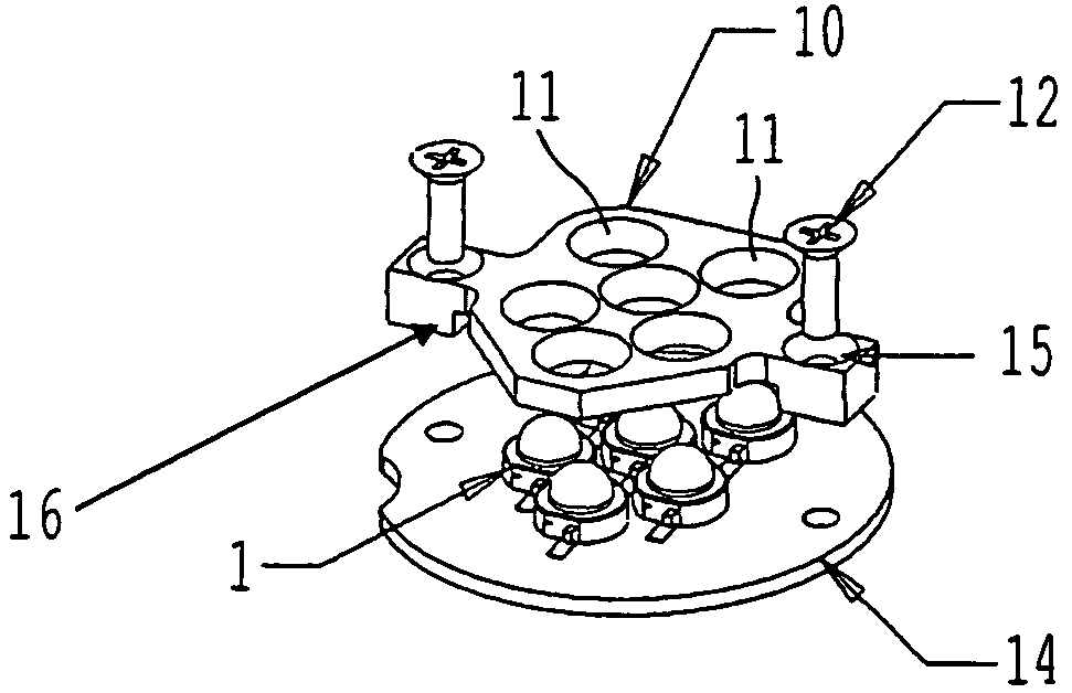
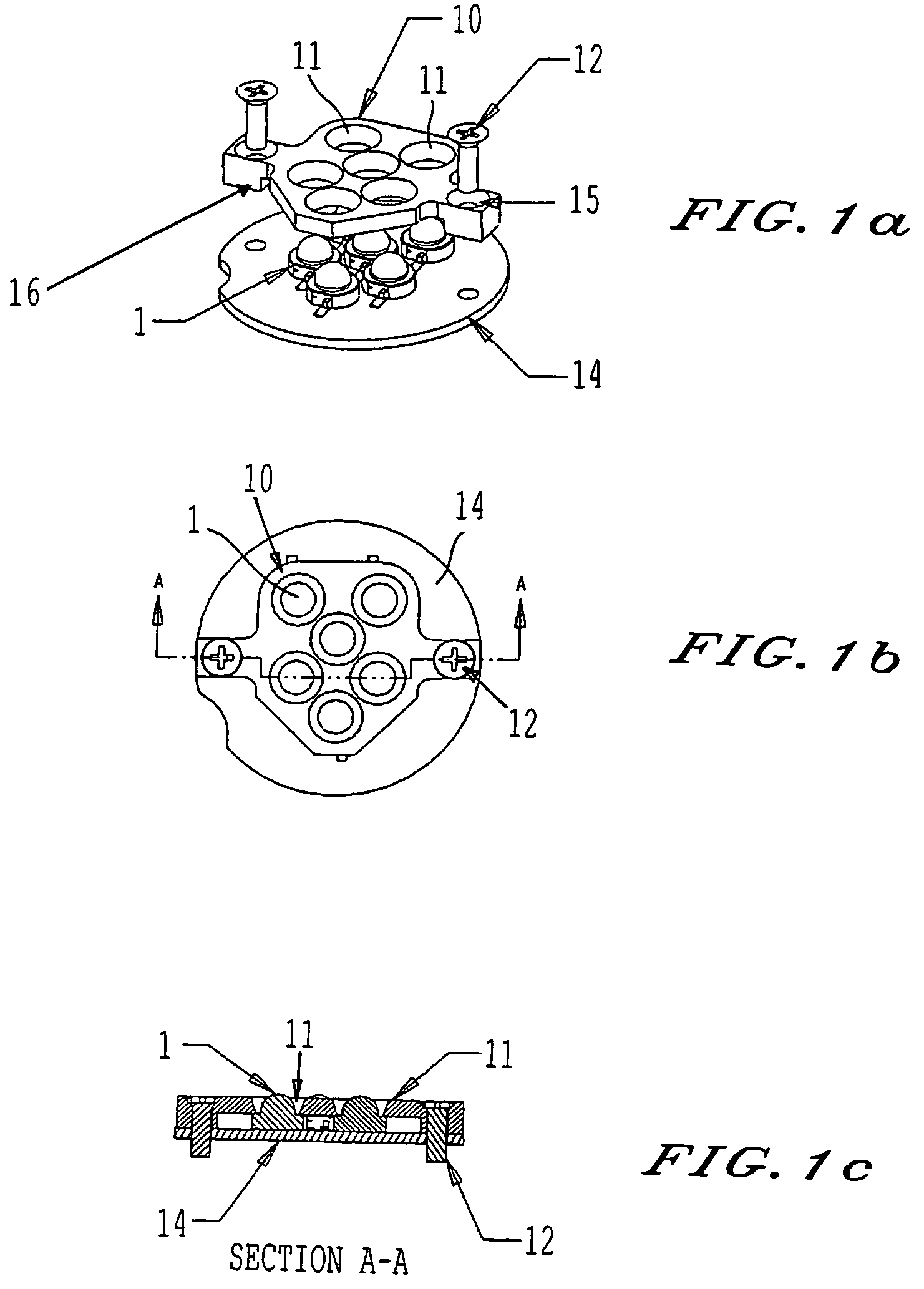
[0029]the present invention is shown in FIGS. 1a-1c.

[0030]As shown in FIGS. 1a-1c a plurality of high-flux LEDs 1 are mounted onto an LED printed circuit board 14. In the embodiment shown in FIGS. 1a-1c a master reflector device 10having individual reflecting portions or reflectors 11 is provided. Those individual reflectors 11 are provided to each surround one respective high-flux LED 1. That is, in this embodiment of the present invention each LED 1 is surrounded by a respective reflector 11 of the master reflector device 10.

[0031]As shown most clearly in FIG. 1c, each individual LED 1 fits inside an individual reflector 11 and walls of the reflector 11 are sloped with respect to the LED 1. That allows light output from sides of the LED 1 to be efficiently reflected. High-flux LEDs have a large viewing angle, meaning that they emit a larger amount of light in divergent directions. By utilizing the master reflector 10 of FIG. 1 light can be reflected by the sloped walls of the ind...


PUM


Abstract

A reflector device to be utilized with light emitting diodes (LEDs), and particularly with high-flux LEDs. In the reflector structure individual reflector portions surround at least one LED. Light output from each individual LED is reflected by sloping walls of each individual reflector portion and is redirected. As a result, light that may otherwise be lost is redirected to a more useful direction. Each individual reflector portion can have a cross-section of a conic shape, a complicated curve, and can also be oval in shape. A light device is realized by utilizing such a master reflector with an LED light source.

Description

FIELD OF THE INVENTION[0001]The present invention is directed to reflectors to utilize with light emitting diodes (LEDs), and particularly when the LEDs are high-flux LEDs.DISCUSSION OF THE BACKGROUND[0002]High-flux LEDs are becoming more and more prevalent. A high-flux LED is generally an LED with greater luminous output in comparison with earlier developed traditional 5 mm LEDs, and an LED that has a larger size chip than in the traditional 5 mm LED. A high-flux LED for the purposes of this disclosure is defined as an individual LED package that is capable of dissipating more than 0.75 watts of electric power. With improvement in high-flux LED technology, more and more companies are developing different types of high-flux LEDs. High-flux LEDs also typically have larger viewing angles in comparison with a traditional 5 mm LED. To use such high-flux LEDs efficiently, mechanisms have been provided to redirected light output from the larger viewing angle of the high-flux LEDs. One kno...

Claims


Application Information

Patent Timeline
Patent Type & Authority Patents(United States)
IPC IPC(8): F21V7/04F21V7/09F21V17/12F21V19/00F21V23/04
CPCF21V7/0083F21V7/09F21V19/0035F21V23/0442F21V23/0457F21V23/005F21V17/12F21Y2105/001F21Y2101/02F21V19/0055F21Y2105/10F21Y2115/10
Inventor YOU, CHENHUAABDELHAFEZ, MOHAMEDYANG, YUBOVERDES, ANTHONYLOMBERG, MARKUSHERTRICH, MICHAEL
Owner DIALIGHT CORP
Why Eureka
Try Eureka