Extrusion/reaction injection molding system

a technology of injection molding and extrusion, which is applied in the direction of dough shaping, hollow wall objects, explosives, etc., can solve the problems of time-consuming and costly, and achieve the effect of high volume parts and economical ra

Inactive Publication Date: 2007-10-16
PATWIN PLASTICS
View PDF33 Cites 29 Cited by
  • Summary
  • Abstract
  • Description
  • Claims
  • Application Information

AI Technical Summary

Benefits of technology

[0009]The present invention combines a polyurethane reactive injection molding (RIM) process with an extrusion process in a manner that provides the ability to produce high volume parts at an economical rate.
[0010]The invention relates to a combined extrusion and reaction injection molding system and method which combines the benefits of the two types of processes. More specifically, the invention combines extrusion technology with reaction injection molding (RIM) technology to produce articles that have, for example, a rigid polyvinylchloride (PVC) exterior shell and a firm, lightweight polyurethane (PUR) inner core.
[0012]The plurality of orifices is preferably configured to evenly distribute the core foam material throughout the interior of the exterior shell. The step of extruding the exterior shell can be used to produce an exterior shell having a plurality of internal chambers, where the orifices of the distribution block are configured to inject core foam material within the plurality of internal chambers. The method of the present invention can allow for the provision of a single set of sizing and cooling sleeves that are utilized to cool the exterior shell and the core foam material.

Problems solved by technology

Some disadvantages of this manufacturing system are they are time consuming and costly.

Method used


Image

  • Extrusion/reaction injection molding system
  • Extrusion/reaction injection molding system
  • Extrusion/reaction injection molding system

Examples


Embodiment Construction

[0025]Embodiments of the present invention will be described hereinafter with reference to the accompanying drawings. In the following description, the constituent elements having substantially the same function and arrangement are denoted by the same reference numerals, and repetitive descriptions will be made only when necessary.

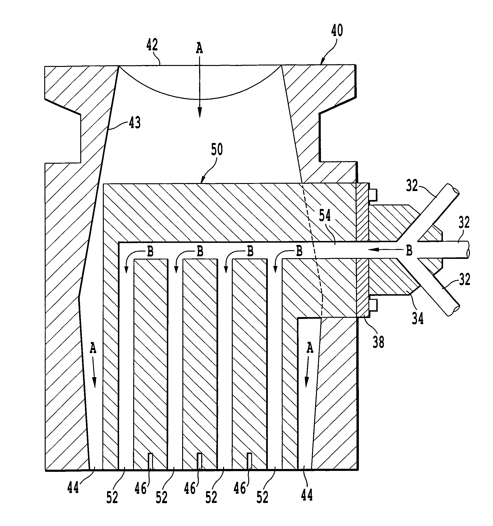
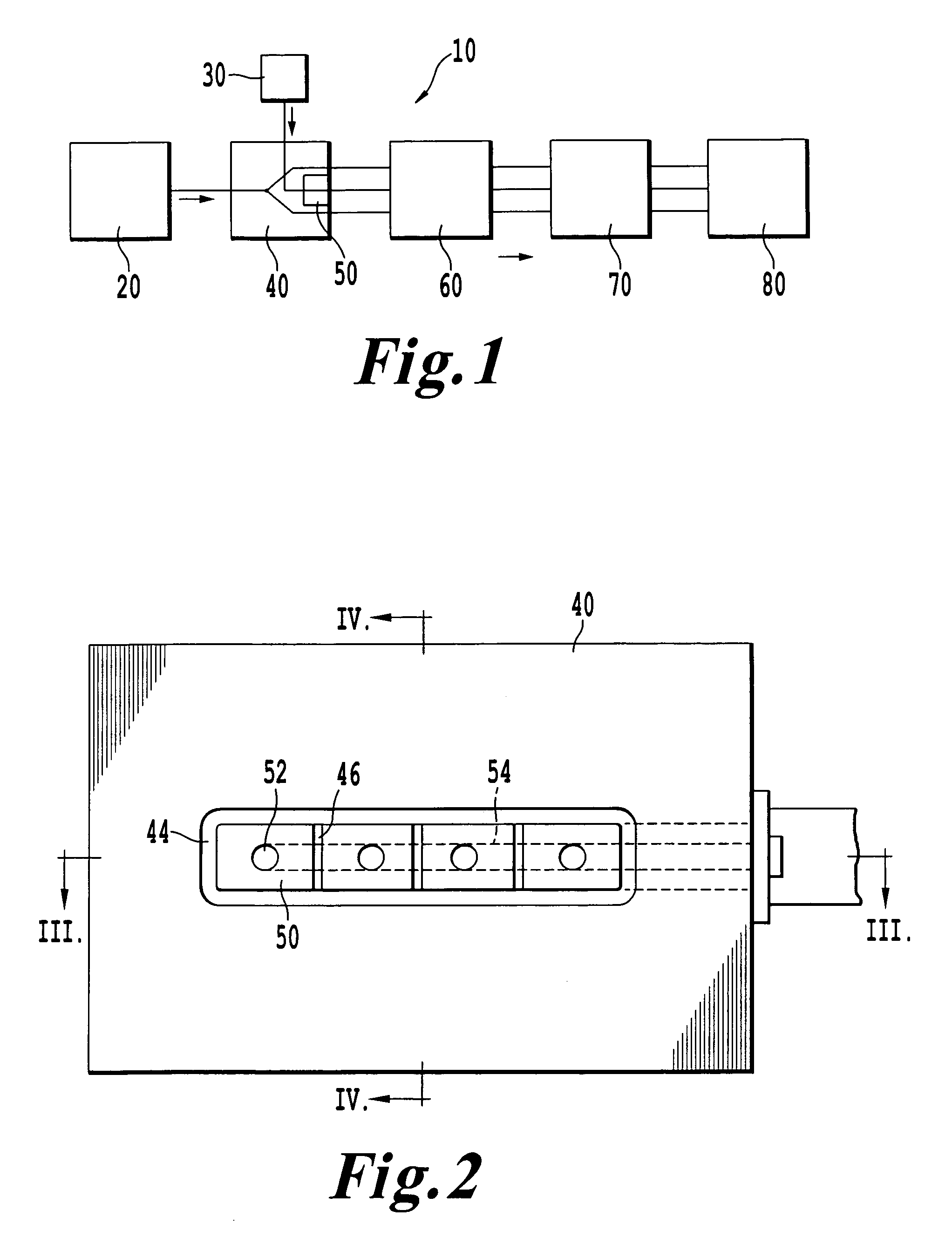
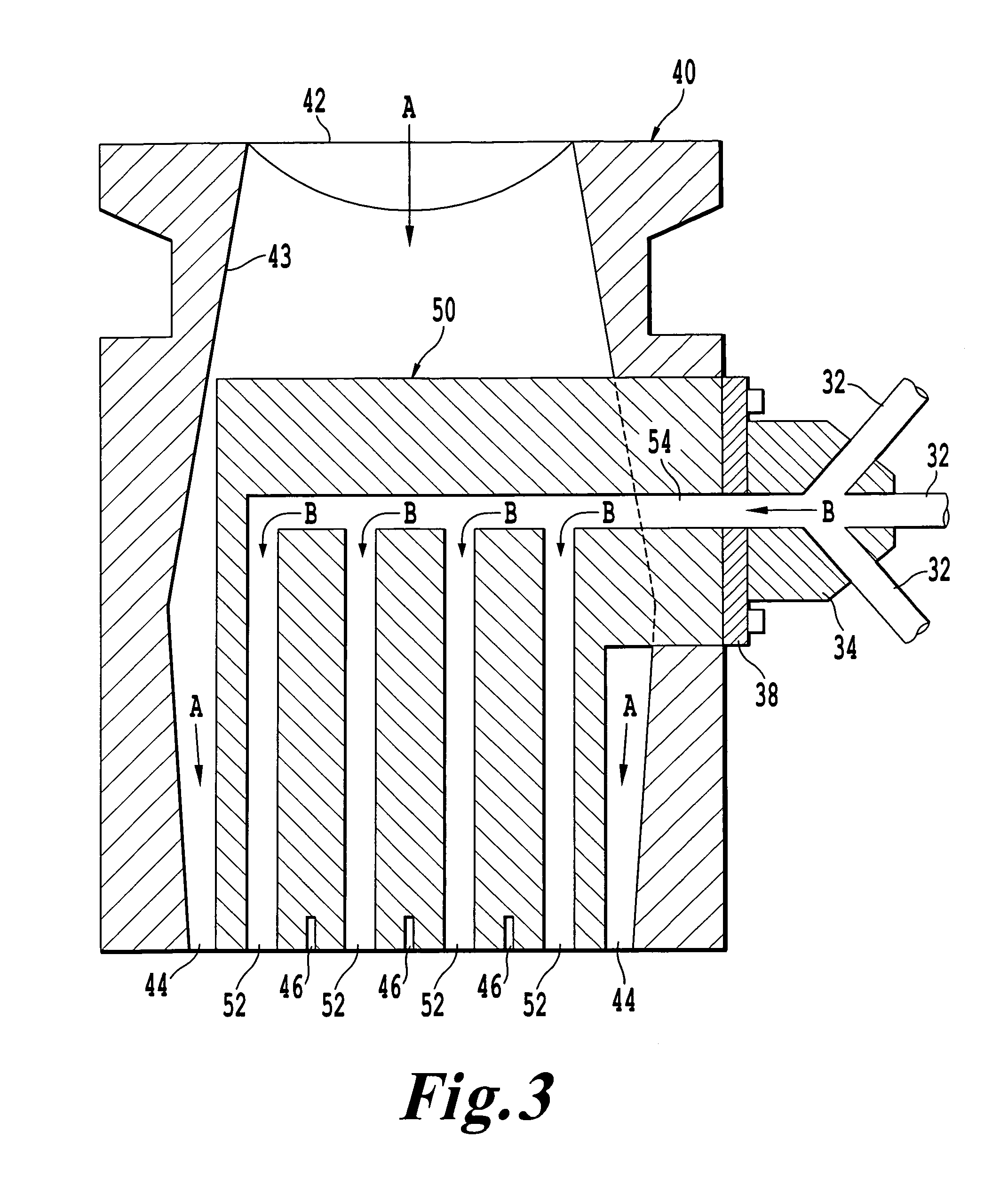
[0026]As mentioned above, the present invention relates to a combined extrusion and reaction injection molding system and method which combines the benefits of the two types of molding processes. More specifically, the invention combines extrusion molding technology with reaction injection molding (RIM) technology to produce molded articles that heave, for example, a rigid polyvinylchloride (PVC) exterior shell and a firm, lightweight polyurethane (PUR) inner core.

[0027]A known benefit of polyurethane is the high strength to weight ratio of the material. Polyurethane is also desirable because of its ability to duplicate parts, such as wood moldings and pla...


PUM

PropertyMeasurementUnit
perimeteraaaaaaaaaa
lengthaaaaaaaaaa
resistanceaaaaaaaaaa

Abstract

A method of manufacturing an extruded part having an exterior shell and a core foam material. The method includes extruding the exterior shell from an extrusion die, and reaction injection molding the core foam material within an interior of the exterior shell using a distribution block having a plurality of orifices configured to inject the core foam material within the interior of the exterior shell. The orifices are configured to evenly distribute the core foam material throughout the interior of the exterior shell. the method can be used to form an exterior shell having a plurality of internal chambers, where the orifices of the distribution block are configured to inject core foam material within the plurality of internal chambers.

Description

BACKGROUND OF THE INVENTION[0001]1. Field of the Invention[0002]The present invention relates to the field of plastic extruded parts.[0003]2. Discussion of the Background[0004]Since it's introduction nearly thirty years ago, the use of polyurethane products has increased dramatically. The use of these products by builders and homeowners alike has increased because of their advantages over wood and other building materials. Their resistance to chemicals, water (including salt water exposure) and insects has made them valuable products to homes and buildings.[0005]These products are produced using a reaction injection molding (RIM) system where two components are combined under high pressure in a mixing head and poured or shot into a mold. The mold can be made from various materials such as silicone, wood or aluminum.[0006]Some disadvantages of this manufacturing system are they are time consuming and costly. The products are produced in a “one at a time” process. The polyurethane sho...

Claims


Application Information

Patent Timeline
Patent Type & Authority Patents(United States)
IPC IPC(8): B29C44/46B29C47/30B29C48/11B29C48/345
CPCB29C44/22B29C47/12B29C47/128B32B3/04B32B3/26B32B5/20B32B27/065B32B27/304B32B27/40B29C47/0028B32B2419/00B29L2024/006B29L2031/60B32B2266/0278B32B2307/714B32B2307/718B29C48/11B29C48/304Y10T428/249953Y10T428/249987
Inventor HANNEN, TIMOTHY J.
Owner PATWIN PLASTICS
Why Eureka
Try Eureka