
Hydraulic control apparatus of automatic transmission

a technology of hydraulic control apparatus and automatic transmission, which is applied in the direction of mechanical actuated clutches, braking components, gearing, etc., can solve the problems of switching valve operation in error, damage to running ability, and failure so as to prevent the operation of switching valves and speed changes. the effect of speed change shock and speed change shock

Inactive Publication Date: 2007-10-16
AISIN AW CO LTD
View PDF2 Cites 27 Cited by
  • Summary
  • Abstract
  • Description
  • Claims
  • Application Information

AI Technical Summary

Benefits of technology

"The present invention provides a hydraulic control apparatus for an automatic transmission that prevents speed change shock without obstructing the improvement of fuel cost and compact formation of the automatic transmission. The apparatus includes a predetermined hydraulic servo for controlling the engagement of a frictional engaging element, a control pressure output element for outputting control pressure and oil pressure, a flow rate regulating element for regulating the flow rate of oil, and a switching valve for selectively switching and outputting the control pressure. The apparatus also includes a first clutch engaged at a low speed stage and a second clutch engaged at a reverse stage in a multistage type transmission. The technical effects of the invention include preventing speed change shock, improving fuel cost, and compact formation of the automatic transmission."

Problems solved by technology

However, for example, when the oil pressure after the engaging operation, i.e., during the engagement, is continuously supplied through the above control valve, there is a fear that running ability is injured if the control valve were to stick.
However, for example, when the oil temperature is high and an engine rotation number is low and the discharge amount of the oil pump is small, there is a fear that problems are caused.
Further, for example, even when the line pressure PL is merely reduced by operating one linear solenoid valve and no switching valve is operated in error, there is also a case in which the line pressure is reduced in flowing the oil into the hydraulic servo of another frictional engagement element and the switching valve is operated in error.
A similar problem is also caused in this case.
However, it is necessary to increase an idling rotation number, the size of the oil pump, etc. to increase the discharge amount of the oil pump.
Accordingly, these increases obstruct the improvement of fuel cost of the vehicle and compact formation of the automatic transmission.

Method used


Image

  • Hydraulic control apparatus of automatic transmission
  • Hydraulic control apparatus of automatic transmission
  • Hydraulic control apparatus of automatic transmission

Examples


Embodiment Construction

[0041]The exemplary embodiments of the present invention will next be explained along the drawings. One example of an automatic transmission able to apply the present invention thereto will first be explained along with FIGS. 6A and 6B. FIGS. 6A and 6B are views showing the automatic transmission 10 in which FIG. 6A is a skeleton view and FIG. 6B is its engaging table.

[0042]As shown in FIG. 6A, for example, the automatic transmission 10 is suitably used in a vehicle of an FF type (front engine, front drive) and has an input shaft 11 of the automatic transmission 10 able to be connected to an unillustrated engine. The automatic transmission 10 also has a torque converter 14 with the axial direction of the input shaft 11 as a center, and a speed change mechanism 13.

[0043]The above torque converter 14 has a pump impeller 14a connected to the input shaft 11 of the automatic transmission 10, and a turbine runner 14b to which rotation of the pump impeller 14a is transmitted through an ope...


PUM


Abstract

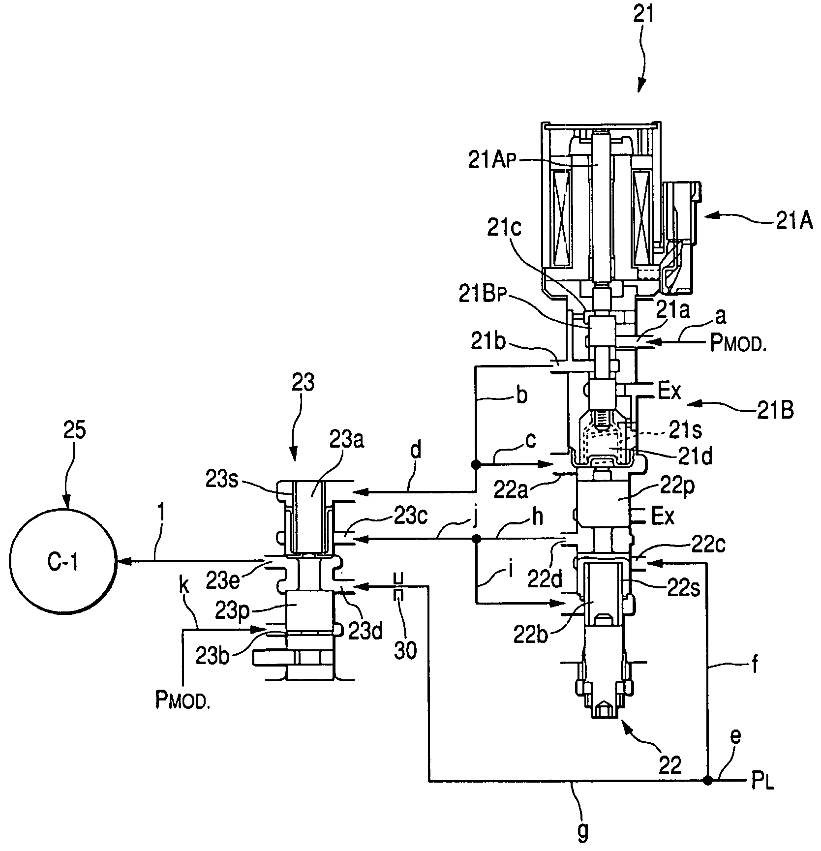
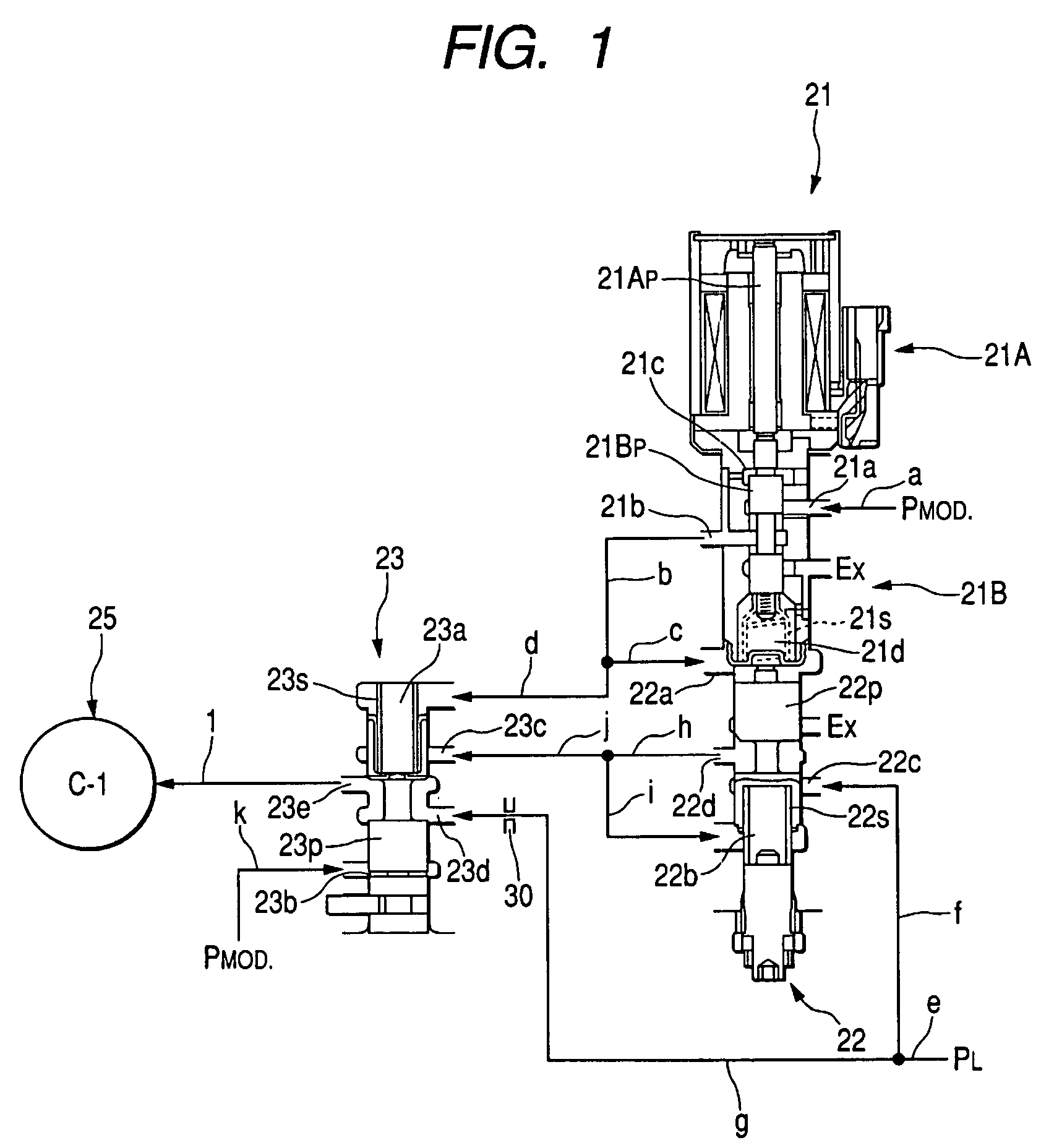
A hydraulic control apparatus of an automatic transmission. The hydraulic control apparatus of the automatic transmission has a hydraulic servo for controlling an engaging state of a clutch C-1 on the basis of supplied oil pressure, a linear solenoid valve for C-1 for outputting signal pressure by adjusting the oil pressure, a control valve for outputting control pressure provided by adjusting line pressure PL on the basis of the signal pressure of the linear solenoid valve for C-1, and a C-1 apply relay valve for inputting, selectively switching and outputting the control pressure and the line pressure PL to the hydraulic servo. An orifice for regulating the flow rate of the oil is arranged in an oil path g for inputting the line pressure PL to this C-1 apply relay valve.

Description

INCORPORATION BY REFERENCE[0001]This application claims the priority of Japanese Patent Application No. 2004-066449 filed on Mar. 9, 2004, the specification, drawings and abstract thereof, are incorporated herein by reference in their entirety.BACKGROUND OF THE INVENTION[0002]1. Field of the Invention[0003]The present invention relates to a hydraulic control apparatus of an automatic transmission for controlling an engaging state of a frictional engaging element in the automatic transmission mounted to, for example, a vehicle, by oil pressure, and more particularly relates to a hydraulic control apparatus of the automatic transmission having a switching valve for selectively switching and supplying control pressure controlled by a solenoid valve and line pressure to a hydraulic servo of the frictional engaging element.[0004]2. Description of the Related Art[0005]The automatic transmission mounted to the vehicle conventionally has the hydraulic control apparatus for controlling the e...

Claims


Application Information

Patent Timeline
Patent Type & Authority Patents(United States)
IPC IPC(8): F16H61/28F16H61/00B60T8/34F16H59/68F16H61/02F16H61/04F16H61/68F16H61/684F16H61/686
CPCF16H61/0206F16H61/04F16H61/12F16H61/686F16H2061/1224F16H2061/205F16H2200/2007F16H2200/2023F16H2200/2097F16H2312/04F16H2200/0052F16H61/00
Inventor SHIMIZU, TETSUYATSUCHIDA, KENICHISUZUKI, AKITOMOISHIKAWA, KAZUNORISHIBAYAMA, YOSHINORI
Owner AISIN AW CO LTD
Learn More