
Tool-switching device

a fast connection and adapter technology, applied in the direction of metal-working holders, positioning apparatuses, supports, etc., can solve the problems of not allowing a large number of electric connections, poor repeatability of positioning, and tool detached from the adapter

Active Publication Date: 2007-10-16
TESA SE
View PDF11 Cites 29 Cited by
  • Summary
  • Abstract
  • Description
  • Claims
  • Application Information

AI Technical Summary

Benefits of technology

The invention is a device that allows for easy switching between different tools on a machine for measuring coordinates. It includes a removable tool-carrier and an adapter that can be attached to the machine. The tool-carrier and adapter have positioning surfaces that create a secure connection between them. The device also has first and second coupling means that can be locked or unlocked to secure the tool-carrier to the adapter. The force exerted during the locking process is aligned with the axis of the tool-carrier. This design makes it simple and easy to switch between different tools on the machine.

Problems solved by technology

These switching devices however have the disadvantage that the tool can become detached from the adapter if the operator forgets to lock the connection.
Some of these switching devices, and notably those that are based on a screw or bayonet connection, suggest a rotation of the tool and do not allow a high number of electric connections between the tool and the measuring machine.
Another disadvantage of the prior art devices, and notably of the devices in which an eccentric acts directly on a fixed element of the adapter, is that the holding force is not oriented along the axis of the tool carrier, or generates torsional or flexional couples, so that during locking, the forces exerted on the positioning surfaces are not distributed symmetrically, which can cause a poor repeatability of the positioning.

Method used


Image

  • Tool-switching device
  • Tool-switching device
  • Tool-switching device

Examples


Embodiment Construction

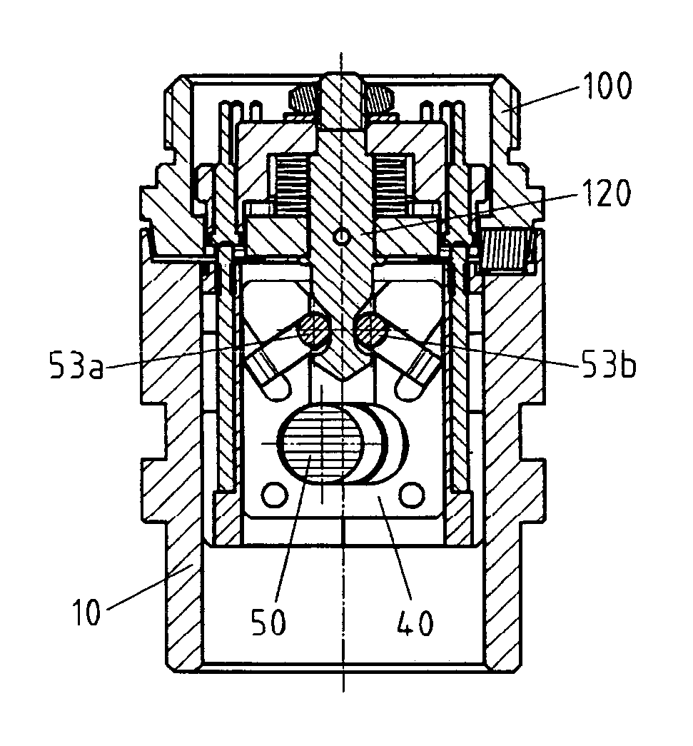
[0032]In a first embodiment of the invention, described now with reference to FIGS. 7 and 8, the inventive device comprises an adapter 100, designed to be fastened to the arm of the measuring machine and a removable tool-carrier 10 for fastening it to the sensor or to the attachment.

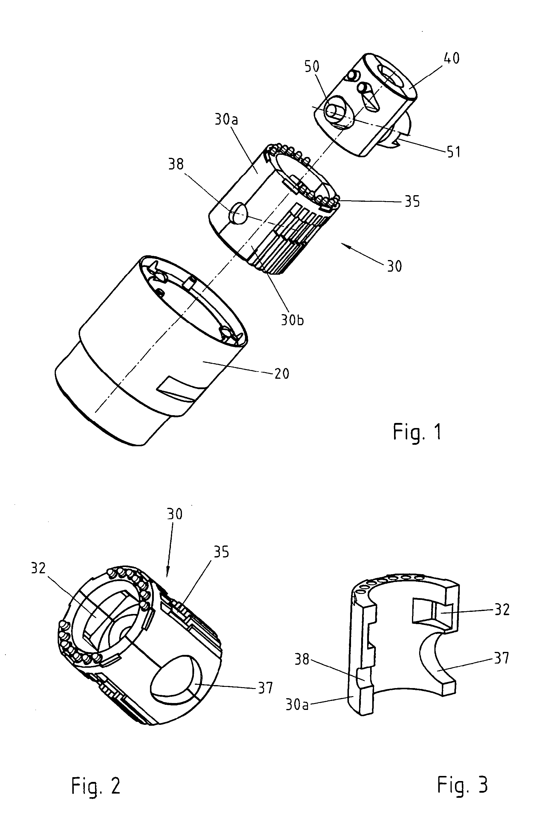
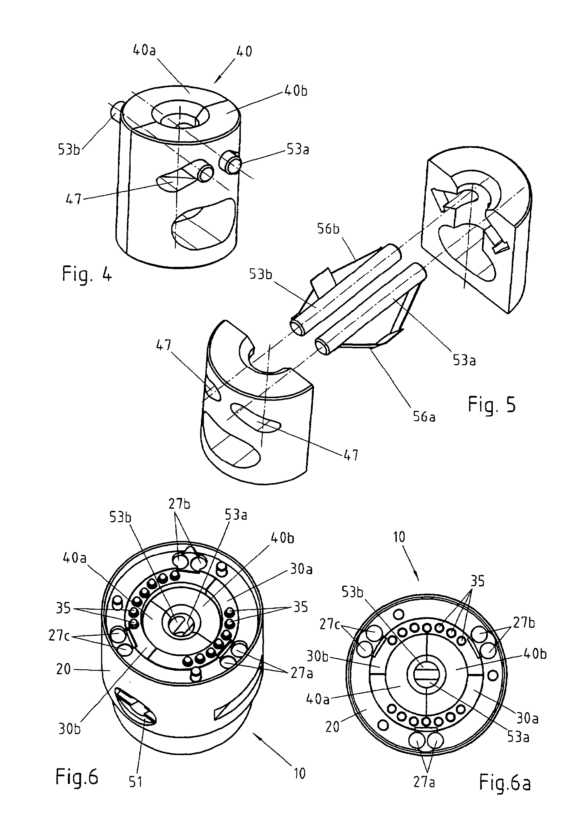
[0033]With reference to the FIGS. 1-5, the tool-carrier 10 comprises a cylindrical body 20, a fixed bushing 30 and a mobile interior bushing 40 capable of sliding inside the fixed bushing 30 and coaxial therewith. In the following, the axis of the bushings 30 and 40 will be designated as “vertical axis”, referring in this to a conventional orientation and only for the purpose of linguistic simplification. The inventive device can be used in any orientation in space.

[0034]To make the assembly and machining easier, each of the bushings 30 and 40 is advantageously made in to parts 30a and 30b, resp. 40a and 40b.

[0035]The connection and disconnection of the adapter 100 and of the tool-carrier 10 are determi...


PUM

PropertyMeasurementUnit
angle of rotationaaaaaaaaaa
temperatureaaaaaaaaaa
forceaaaaaaaaaa

Abstract

Tool-switching device for a machine for measuring coordinates wherein the tool is fastened on the tool-carrier and held by the action of elements exerting an axial force. The locking force is taken over symmetrically by the elements of a Boys connection, which increases the repeatability of the connection; in one embodiment, two pins or spheres are driven by a sliding bushing provided with two “V”-shaped slits or with two lateral gorges. In the subsequent embodiments, the pins are replaced by spheres, by levers or by a stirrup.

Description

REFERENCE DATA[0001]This application claims priority from European patent application 2004EP-101125 filed on Mar. 18, 2004, the contents whereof are hereby incorporated by reference.FIELD OF THE INVENTION[0002]The present invention pertains to a fast connection device for connecting two mechanical elements in accurate and repeatable fashion, by manual action or under the action of an appropriate servomechanism.DESCRIPTION OF RELATED ART[0003]The present invention is suited especially, though not exclusively, for connecting a touch sensor and an articulated head of a machine for measuring coordinates. However, the type of connection of the invention could just as well apply to a large number of different situations where a mechanical connection that is both fast and accurate is required. In particular, the device of the present invention can for example be used for connecting a video camera or for any other known sensor.[0004]Devices enabling the tools of a machine for measuring coor...

Claims


Application Information

Patent Timeline
Patent Type & Authority Patents(United States)
IPC IPC(8): B23Q3/155B23B31/171G01B5/008G01B7/008G01B5/004B23B35/00B23Q1/00F16D1/033G01B7/00
CPCB23Q1/0072Y10S483/901Y10T279/17752Y10T279/17717Y10T483/17Y10T483/18Y10T408/96G01B21/047
Inventor JORDIL, PASCALROUGE, CLAUDEVUILLOUD, BENJAMINZANIER, ADRIANO
Owner TESA SE
Learn More