Integrated reverse battery protection circuit for an external MOSFET switch

a reverse battery protection and switch technology, applied in circuits, emergency protection circuit arrangements, electrical equipment, etc., can solve the problems of severe damage to integrated circuits connected to power supplies without any form of reverse bias protection, excessive power consumption, and inability to reverse bias protection. to achieve the effect of less resistance, less energy consumption, and limited power dissipation

Active Publication Date: 2007-10-16
TEXAS INSTR INC
View PDF4 Cites 36 Cited by
  • Summary
  • Abstract
  • Description
  • Claims
  • Application Information

AI Technical Summary

Benefits of technology

[0011]To address the above-discussed deficiencies of reverse battery protection circuits, the present invention teaches a reverse battery protection circuit that provides an integrated reverse battery condition solution for protection of external NMOS switches during the reverse battery condition. This reverse battery protection circuit minimizes power consumption during a reverse battery event wherein there is no need for mechanical adjustments such as heat sinking and clamping to extract the heat away from the silicon and not destroy the device. In addition, this novel design protects the external FET devices during the reverse battery condition without the use of a reverse blocking diode.
[0014]An objective of this design is to turn the external FET on such that the power dissipation is limited due to the intrinsic diode of the external FET. In this condition, the current path generated by the reverse battery condition is less resistive and therefore dissipates less energy.

Problems solved by technology

It is common for the power supply battery to be inadvertently reversed, thereby reversing the bias of the applied potential difference.
As a result, severe damage to integrated circuits connected to the power supply occurs without any form of reverse bias protection between the integrated circuit and the applied potential difference.
Moreover, this extreme condition of reverse battery can cause excessive power consumption.
Yet, during the reverse bias condition, damage will result.
These components, however, tend to pass the same amount of large current as the big pass transistor.
Thereby, current-limiting resistors, diodes and MOS transistors connected in series with the big pass transistor may cause undesired voltage drops.
The voltage drop across the diode, however, reduces the actual DC voltage available to the integrated.
Presently, there is no known design that will protect external components.
This power expenditure caused by the reverse battery condition affects functionality and reliability of the system including this IC and external drive FET.

Method used


Image

  • Integrated reverse battery protection circuit for an external MOSFET switch
  • Integrated reverse battery protection circuit for an external MOSFET switch

Examples


Embodiment Construction

[0020]One or more exemplary implementations of the present invention will now be described with reference to the attached drawings, wherein like reference numerals are used to refer to like elements throughout. The various aspects of the invention are illustrated below in a reverse battery, although the invention and the appended claims are not limited to the illustrated examples.

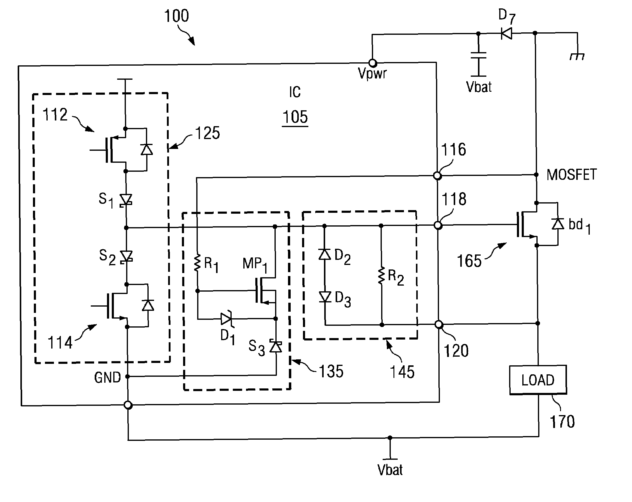
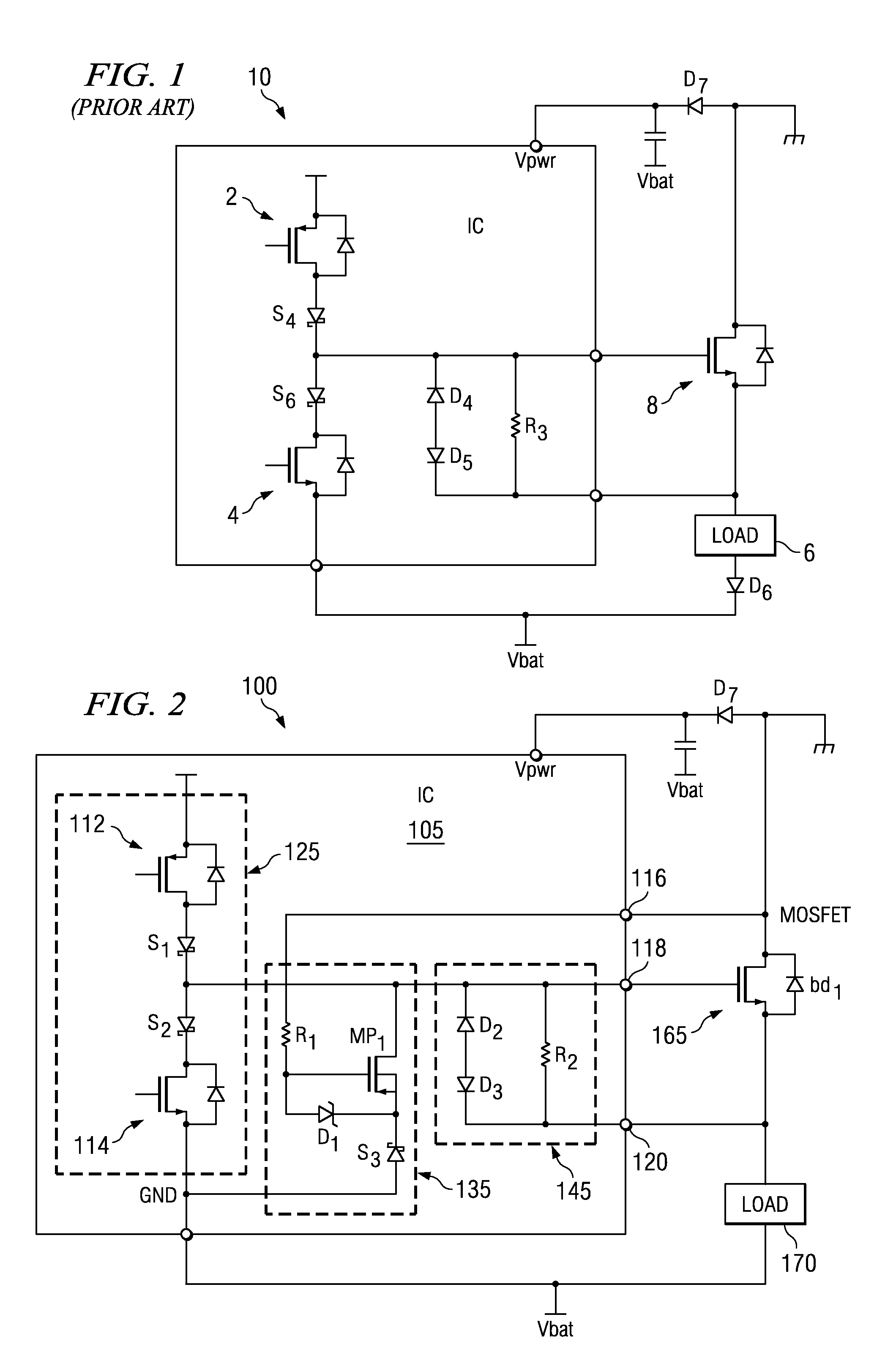
[0021]As shown in FIG. 2, a reverse battery is applied to the external FET 165, where voltage of the battery Vbat is being applied to the ground pin GND and the ground pin GND is being applied to the power side of the external FET 165. This condition represents the well-known reverse battery condition. Typically, it is a gross mistake where a module that includes the IC has been plugged in inappropriately or where battery cables are reversed, i.e. in a hypothetical jump start of an automobile. Without the protection of the reverse battery protection circuit 100 in accordance with the present invention, one ...


PUM


Abstract

A reverse battery protection circuits that provides an integrated reverse battery condition solution for protection of external NMOS switches during the reverse battery condition is disclosed herein. This reverse battery protection circuit minimizes power consumption during a reverse battery event wherein there is no need for mechanical adjustments such as heat sinking and clamping to extract the heat away from the silicon and not destroy the device. Specifically, the reverse battery protection circuit includes a push-pull gate drive circuit coupled between the first and second power supply rail. A protection subcircuit portion connects between a first output node and the second power supply rail to turn the external FET ‘on’ during the reverse battery condition. In particular, the protection subcircuit portion connects to the external FET device and includes a p-channel device connected between a second output node that biases the external FET device and a first diode. A resistor connects between a first output node of the reverse battery protection circuit to provide a voltage drop between the drain terminal and the gate of the p-channel device. A second diode connects between the gate and the source of the p-channel device. In addition, a clamping circuit connects between the second output node and the third output node to provide clamping in the instance where the voltage at the second output node momentarily rises too high.

Description

FIELD OF THE INVENTION[0001]The present invention relates to reverse battery protection circuits and, more particularly, a reverse battery protection circuit for an external MOSFET switch.BACKGROUND OF THE INVENTION[0002]Operation of all integrated circuits (ICs) depends upon a power supply having a potential difference for use in powering internal integrated circuit components to ensure their operation. It is common for the power supply battery to be inadvertently reversed, thereby reversing the bias of the applied potential difference. In the automotive industry, for example, during a jump start, a battery may be mistakenly connected backwards to a circuit wherein the negative supply connects to the positive power rail and the positive supply connects to the negative power rail. As a result, severe damage to integrated circuits connected to the power supply occurs without any form of reverse bias protection between the integrated circuit and the applied potential difference. Moreo...

Claims


Application Information

Patent Timeline
Patent Type & Authority Patents(United States)
IPC IPC(8): H02H3/18
CPCH02H11/002
Inventor GROSE, WILLIAM E.LEGAT, TIMOTHY J.PATEL, SANMUKH M.
Owner TEXAS INSTR INC
Why Eureka
Try Eureka