Shaftless radial vane rotary device and a marine propulsion system using the device

a rotary device and radial vane technology, applied in the direction of motor-driven power plants, special-purpose vessels, vessel construction, etc., can solve the problems of difficult and expensive production of the vane-supporting slots of the known device, the device has not met with wide-spread acceptance, and all of the above would appear to present severe maintenance problems

Inactive Publication Date: 2007-10-23
SEIFORD SR DONALD S
View PDF5 Cites 3 Cited by
  • Summary
  • Abstract
  • Description
  • Claims
  • Application Information

AI Technical Summary

Benefits of technology

[0029]In a first embodiment, a plurality diameter reducing elements or ramps, are mounted on the inner surface of the stator and extend the length thereof between the thrust bearings. The ramps have arcuate inner and outer surfaces concentric with the opposed stator and rotor cylindrical surfaces, and have their longitudinal edges tapered to provide ramp areas enabling the contact member of the vanes to be cammed inwardly and to smoothly expand as the rotor rotates in the stator.
[0034]A support post, preferably in the form of cylindrical pipe or tube, is rigidly joined, as by welding, to the outer periphery of the stator for supporting the motor and propeller. This support post may extend through the hull of a vessel and be mounted for rotation about its longitudinal axis to turn the motor and propeller in any direction, thereby eliminating the need for a rudder to steer the vessel or the need to stop and reverse the motor for backing thrust. Also, the pressure conducts connected to the pressure channels, which conduits preferably pass through the support post, are capable of being rotated, as by a suitable swivel connection. Alternatively, flexible conduits may be employed which enable limited rotation of the propeller and motor about the support post axis. By rotating the motor and propeller through 180°, reverse thrust is applied to the support post. Alternatively, the motor and propeller may be reversed by reversing the flow of hydraulic fluid through the motor.

Problems solved by technology

The vane-supporting slots of the known device have been difficult and expensive to produce in that they have generally been machined into a relatively large body of rigid material, usually metal, and smooth surfaces are necessary to minimize friction with the sliding vanes.
While the rimmed propellers of the prior art, discussed above, would appear to be efficient in converting the propeller drive force to thrust, these devices have not met with wide-spread acceptance for various reasons.
For example, all would appear to present severe maintenance problems, particularly in the use of sleeve bearings or the like for transmitting thrust, as well as in providing adequate lubrication of movable parts.
The prior art sealing arrangements, particularly for electrically driven systems, present serious problems.
Further, the known rim mounted propellers generally require separate rudder systems for steering, and generally have not been energy efficient.
Another objection is to provide an improved radial vane rotary device having spring-loaded vanes supported for substantially radial movement on the rotor, which vanes have pressure ports and / or shuttle valves for assisting the springs in maintaining the vanes in contact with stator surface while assuring freedom of movement of the vanes during rotation of the rotor.

Method used


Image

  • Shaftless radial vane rotary device and a marine propulsion system using the device
  • Shaftless radial vane rotary device and a marine propulsion system using the device
  • Shaftless radial vane rotary device and a marine propulsion system using the device

Examples


Embodiment Construction

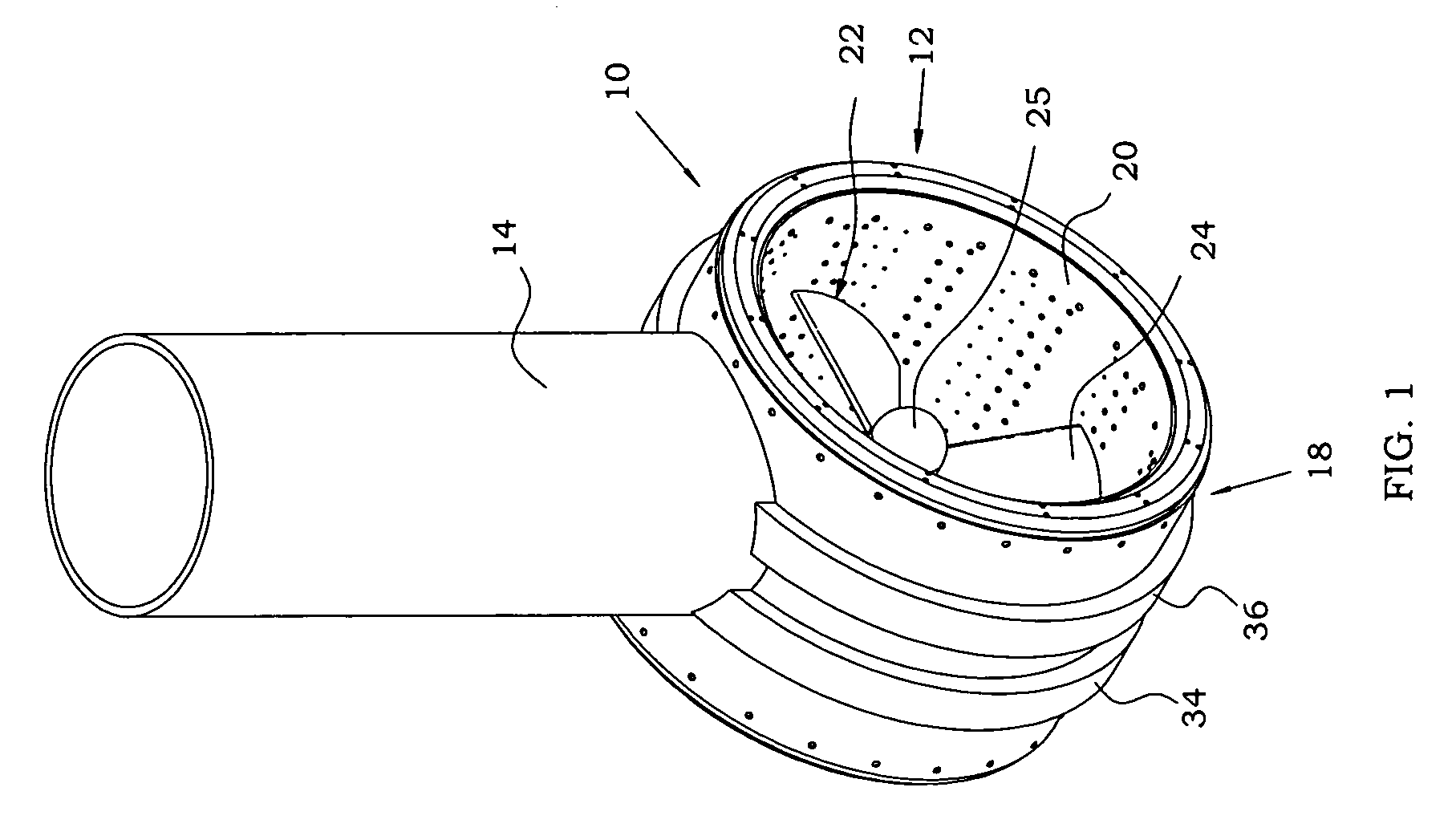
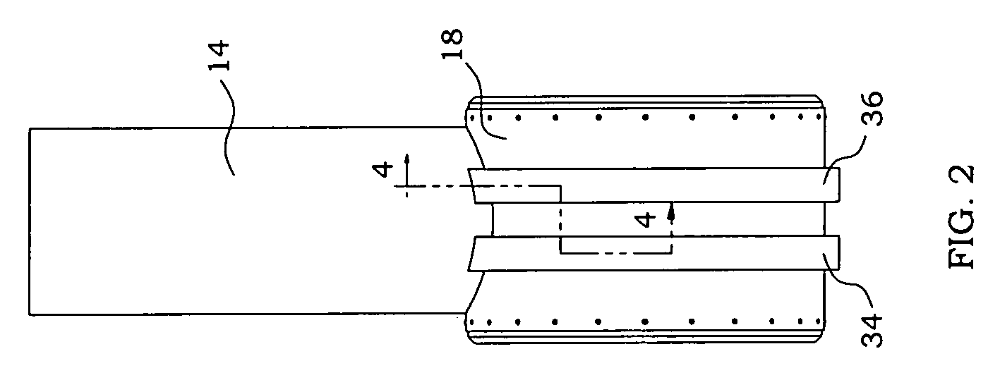
[0051]Referring now to the drawings in detail, a first embodiment of a radial vane rotary motor embodying the invention is illustrated as a drive unit for a marine propulsion system designated generally at 10 in FIG. 1, and includes a cylindrical tubular hydraulic motor 12 supported on a hollow, preferably cylindrical support post 14 which, in use, projects through the hull of a vessel (not shown) and is supported for pivotal or rotary movement about its longitudinal or vertical axis 16. The motor 12 consists of a generally cylindrical stator 18 rigidly mounted, as by welding, on the downwardly projecting end of support post 14, and a rotor 20 rotatably mounted in stator 18.

[0052]As best seen in FIGS. 1 and 3, the rotor 20 includes a propeller 22 having a plurality of blades 24 supported on a hub 25. Propeller 22 may be of a standard or commercial marine propeller design, with the tips of the blades 24 rigidly joined, as by welding or bolting, to the inner periphery of a tubular rot...


PUM


Abstract

A radial vane fluid motor or pump has an open ended tubular rotor having a cylindrical outer surface rotatably mounted in a tubular stator having its inner surface contoured to provide successive portions of increased and decreased spacing relative to the rotor body. A plurality of elongated movable vane assemblies are mounted on and project outwardly from the rotor surface to continuously contact the stator surface. Bearings support the rotor within the stator, and seals are provided for sealing the space between the rotor and stator. Pressure inlets and exhaust ports are provided in the stator to permit the flow of pressure fluid into or out of the device. Mounting the vanes on the cylindrical rotor surface enables production cost reduction and simplifies maintenance. A conventional propeller mounted in the cylindrical rotor provides an improved shrouded propellor propulsion system for marine vessels. Mounting the system on a vessel for rotation about an axis perpendicular to the axis of the rotor enables steering of the vessel without use of a rudder.

Description

CROSS-REFERENCE TO RELATED APPLICATIONS[0001]This application is based on U.S. Provisional Application No. 60 / 594,394 filed on Apr. 4, 2005.BACKGROUND OF THE INVENTION[0002]1. Field of the Invention[0003]This invention relates to an improved shaftless radial vane rotary device such as a fluid motor, fluid pump, compressor or the like, and to an improved marine propulsion system using the device as a drive motor. The propulsion system includes a propeller having its blade tips rigidly joined to the inner periphery of an open-center tubular rotor of the device, with the stator being adapted to be joined to and supported on the hull of a marine vessel.[0004]2. Description of the Prior Art[0005]Radial vane rotary devices such as motors, pumps and compressors are known in which a plurality of equally spaced vanes are mounted in radial slots in a cylindrical rotor body and are biased outwardly from the rotor into contact with the inner surface of a stator. Various configuration of the rot...

Claims


Application Information

Patent Timeline
Patent Type & Authority Patents(United States)
IPC IPC(8): B63H25/46
CPCB63H1/16B63H5/14F04C2/344B63H23/26B63H2023/005F01C21/0845
Inventor SEIFORD, SR., DONALD S.
Owner SEIFORD SR DONALD S
Why Eureka
Try Eureka