
Method of dispensing pulverulent contents and apparatus for implementing this method

a technology of pulverizing contents and apparatus, which is applied in the direction of liquid dispensing, liquid/fluent solid measurement, and opening closed containers, etc., can solve the problems of unusable residual quantity of contents remaining in the bottom hopper-like base region, unusable residual quantity of contents which cannot be used with difficulty, undesirable to use this residual quantity, etc., and achieves short operating cycle

Active Publication Date: 2007-10-23
HARRO HOFLIGER VERPACKUNGSMASCHEN
View PDF14 Cites 24 Cited by
  • Summary
  • Abstract
  • Description
  • Claims
  • Application Information

AI Technical Summary

Benefits of technology

[0007]Taking this prior art as the departure point, the object of the invention is to specify a possible way of dispensing pulverulent contents which allows, as far as possible, constant quantities of pulverulent contents to be dispensed by as straightforward and compact a dispensing apparatus as possible, the intention being for this dispensing apparatus to be straightforward to handle during operation. Nevertheless, the dispensing operation using such a dispensing apparatus is to be capable of being carried out as cost-effectively as possible.
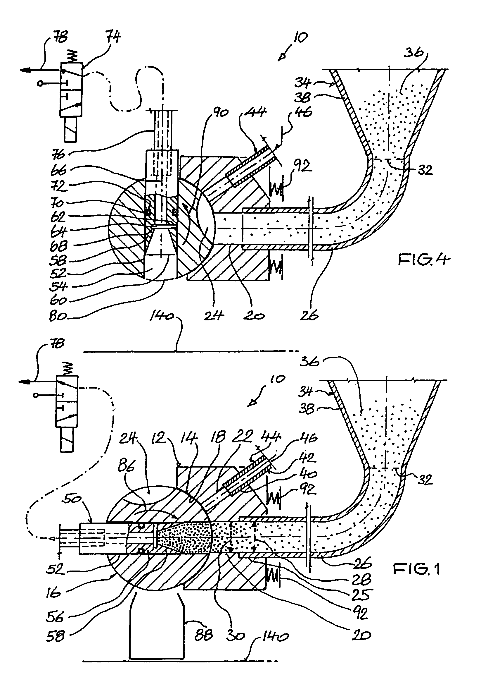
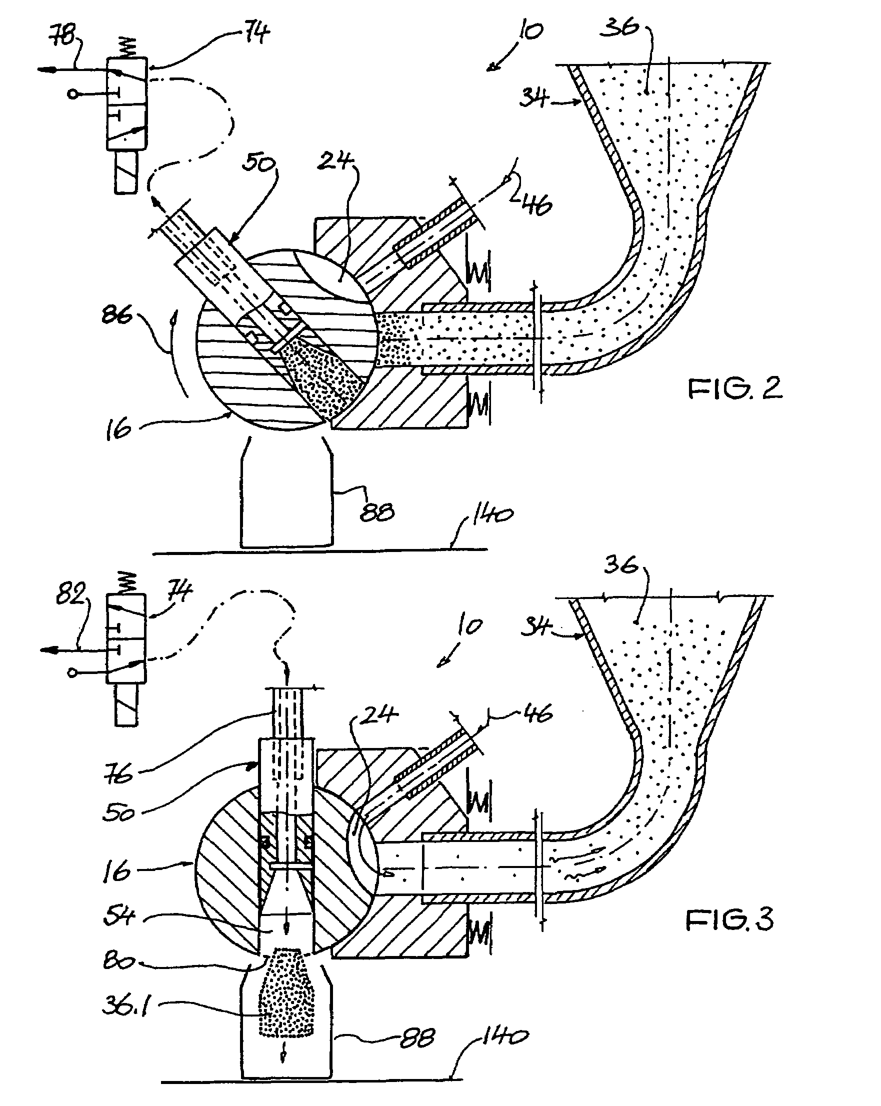
[0009]The invention is distinguished, in particular, in that the metering roller itself also functions as a kind of closing valve for the gas line serving for fluidizing the contents present in the material store, in that, in dependence on the respective rotary position of the metering roller, this gas line is or is not closed by the metering roller. The duration of the individual dispensing cycles thus does not depend on any actual valve arrangements for opening and closing such a gas line. Furthermore, the absence of such valve arrangements also reduces the cleaning outlay for the dispensing apparatus according to the invention.
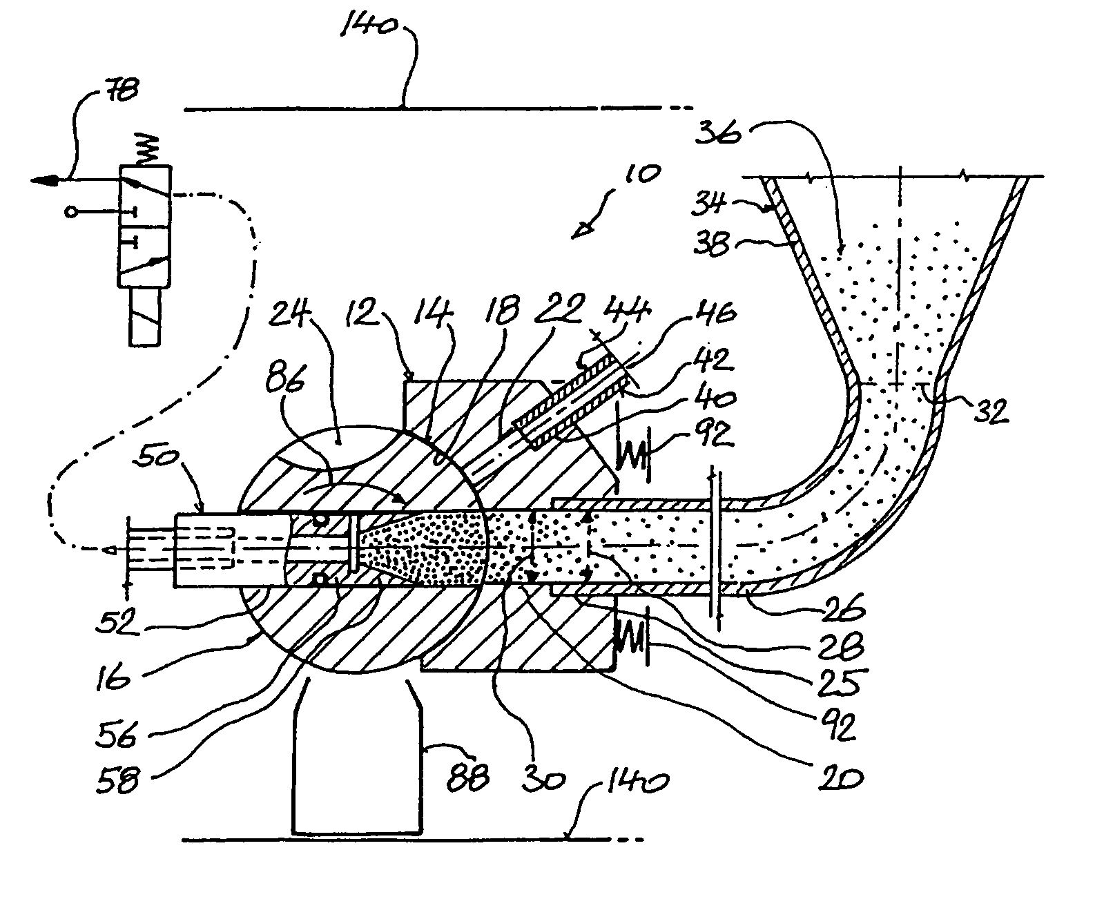
[0011]A first type of dispensing apparatus according to the invention has a metering roller which contains at least one lateral line. This at least one lateral line is not line-connected to the metering chamber. Depending on the rotary position of the metering chamber, a line connection between the material store which stores the pulverulent contents and the gas line serving for fluidizing the contents stored in the material store may or may not be produced via this lateral line. It is thus possible, within a relatively long period of each dispensing cycle, for the material store to be subjected to the action of fluidizing gas. This allows very short operating cycles.

Problems solved by technology

On account of the metering roller positioned above the base opening of the hopper-like material store, it is not possible for the contents present in the base region of the material store to be removed in their entirety from the material store; between the base opening of the material store and the metering chamber positioned thereabove, there is always an unusable residual quantity of contents remaining in the bottom hopper-like base region of the material store.
Since it cannot be ensured whether, and when, this residual quantity is sucked back into the metering chambers, this residual quantity constitutes a quantity of contents which can only be used with difficulty, if at all.
It is frequently also the case that it is undesirable to use this residual quantity since, in particular in the case of medicaments which are to be dispensed, timely dispensing is necessary if decomposition or some other negative change in the powdered medication as the latter resides in the material store over a relatively long period of time is to be avoided.
The oscillating movement of the powder container is disadvantageous, this precluding a high dispensing performance.
In particular, however, the arrangement of the very large number of gas-introduction tubes in the powder container proves to be disadvantageous in design terms.
The porous walls prove to be particularly disadvantageous since, during the processing of contents which are to be handled very carefully, in particular pharmaceutical powders, the latter, if fine-grained enough, can settle in the porous walls.
This results in it no longer being possible to guarantee hygienic dispensing.
The problem here is the unavoidable effect of the shearing operation precluding the respective quantities of powder from being separated off precisely from one another.
This results in relatively large fluctuations in the quantities of powder which are to be dispensed in each case, which is undesirable, for example, in the case of dispensing medicaments.
It is also possible, on account of the flexing movements of the hose wall brought about during the pinching operation and of the resulting pronounced material fatigue of the hose, for particles to be detached therefrom and then to be included in the dispensing operation; this is unacceptable in the operation of dispensing a medicament.

Method used


Image

  • Method of dispensing pulverulent contents and apparatus for implementing this method
  • Method of dispensing pulverulent contents and apparatus for implementing this method
  • Method of dispensing pulverulent contents and apparatus for implementing this method

Examples


Embodiment Construction

[0007]Taking this prior art as the departure point, the object of the invention is to specify a possible way of dispensing pulverulent contents which allows, as far as possible, constant quantities of pulverulent contents to be dispensed by as straightforward and compact a dispensing apparatus as possible, the intention being for this dispensing apparatus to be straightforward to handle during operation. Nevertheless, the dispensing operation using such a dispensing apparatus is to be capable of being carried out as cost-effectively as possible.

[0008]This invention is achieved, in respect of the method according to the invention, by the features of claim 1 and, in respect of an apparatus according to the invention, on which this method is to be implemented, by the features of claim 5. Expedient developments both of the method and of the apparatus form the subject matter of further claims which follow claims 1 and 5 in each case.

[0009]The invention is distinguished, in particular, in...


PUM


Abstract

An apparatus for dispensing respectively predetermined quantities of pulverulent contents has a rotatably drivable metering roller containing at least one metering chamber and a material store which stores the pulverulent contents. The metering roller contains at least one lateral line, which is not line-connected to the metering chamber and of which the at least two line ends terminate on the surface of the metering roller. A gas line is guided into the housing and passes out of the housing again in a concave surface region. Gas is introduced into the material store via the lateral line, in dependence on the respective rotary position of the metering roller, through said gas line. Depending upon the rotary positions of the metering roller, the gas line, which fluidizes the contents present in the material store, is closed or opened by the metering roller.

Description

TECHNICAL FIELD[0001]The invention relates to a method of, and an apparatus for, dispensing respectively predetermined quantities of pulverulent contents. The respective dispensing quantities are to be as constant as possible. The contents which are to be dispensed in each case are introduced into a metering chamber and transported from the latter to a container which is to be filled in each case. The contents present in the metering chamber are then emptied into such an available container.[0002]Such dispensing devices may be designed as so-called metering tubes or as a metering roller. Whereas a metering tube, for filling purposes, is inserted from above into a stationary bed of bulk material, the metering chambers, which are distributed over the outer circumference of a metering roller, are positioned one after the other beneath the base opening of a contents-storing material store during the respective filling operation.PRIOR ART[0003]U.S. Pat. No. 5,826,633 discloses a metering...

Claims


Application Information

Patent Timeline
Patent Type & Authority Patents(United States)
IPC IPC(8): G01F11/00B65B1/16B65B1/36B65B1/38
CPCB65B1/16B65B1/385B65B1/366Y10T137/86871
Inventor ZILL, TOBIASREISER, MANFRED
Owner HARRO HOFLIGER VERPACKUNGSMASCHEN
Learn More