Ophthalmic apparatus and corneal surgery apparatus

a corneal surgery and ophthalmic technology, applied in the field of ophthalmic apparatus and corneal surgery apparatus, can solve problems such as halo or glare, and achieve the effect of unerring accuracy

Active Publication Date: 2007-10-23
NIDEK CO LTD
View PDF16 Cites 24 Cited by
  • Summary
  • Abstract
  • Description
  • Claims
  • Application Information

AI Technical Summary

Problems solved by technology

However, there are some cases where the pupil center position in photopia is not necessarily equal to that in scotopia (i.e. the pupil of the eye is dilated) according to individual circumstances.
Therefore, the laser irradiation based on the pupil center position of the eye in photopia tends to cause a halo or glare when the eye is in scotopia.

Method used


Image

  • Ophthalmic apparatus and corneal surgery apparatus
  • Ophthalmic apparatus and corneal surgery apparatus
  • Ophthalmic apparatus and corneal surgery apparatus

Examples


Embodiment Construction

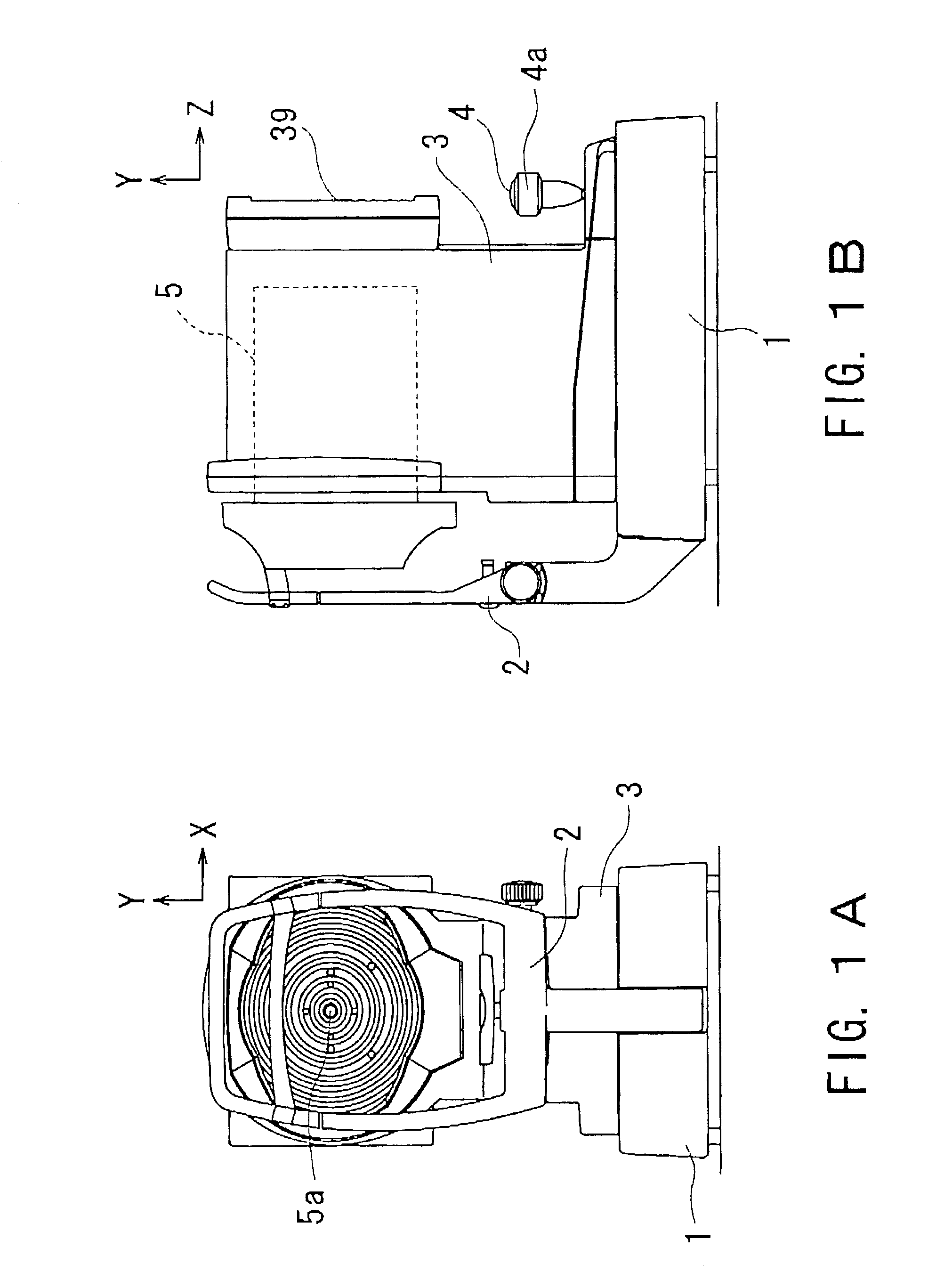
[0024]A detailed description of one preferred embodiment of an ophthalmic apparatus and a corneal surgery apparatus embodying the present invention will now be given referring to the accompanying drawings. FIGS. 1A and 1B are views schematically showing an external configuration of the ophthalmic apparatus consistent with the present invention; FIG. 1A is a front view seen from an examinee's side, and FIG. 1B is a side view.

[0025]On a fixation base 1, a head supporting part 2 is mounted securely in order to fix the examinee's head. In a measurement part 5, optical systems and other systems are stored. A measurement window 5a through which light passes is provided approximately at the lateral center on the side facing the examinee. When a joystick 4 is tilted backward / forward and rightward / leftward, a main body 3 incorporating the measurement part 5 slides and moves backward / forward and rightward / leftward (in Z and X directions) on the fixation base 1. In addition, when a rotation kn...


PUM


Abstract

An ophthalmic apparatus for obtaining differences between the pupil positions in photopia and scotopia accurately, and a corneal surgery apparatus for ablating a cornea of an eye by laser beam irradiation allowing for the differences. The ophthalmic apparatus has devices for inputting a first image of an anterior eye segment in photopia and a second one in scotopia, for obtaining pupil information in the images and differences between the pupil information in photopia and that in scotopia, and for outputting the differences. The corneal surgery apparatus has devices for irradiating the cornea with a laser beam, for aligning an irradiation position with the eye, for inputting differences between the pupil positions in photopia and scotopia, for detecting the photopic pupil position, for obtaining an alignment position of the laser beam based on the pupil position and the positional difference, and for controlling the alignment device based on the alignment position.

Description

BACKGROUND OF THE INVENTION[0001]1. Field of the Invention[0002]The present invention relates to an ophthalmic apparatus and a corneal surgery apparatus used in ophthalmic clinics and the like.[0003]2. Description of Related Art[0004]On ophthalmic diagnosis, examination, treatment and prescription, it is sometimes necessary to obtain information about the position and / or shape of a pupil. For example, in corneal surgery for correcting refractive power by ablating a cornea with a laser beam, it is common practice to align a reference axis of irradiation of the laser beam with the position of a pupil center.[0005]In addition, among multifocal contact lenses, in which different lens diopters are provided in the form of concentric circles around an axis of an optical center of the lens, there are some in which the axis of the optical center is decentered with respect to the geometric center of the lens. The amount of the decentering is determined in consideration of the pupil center pos...

Claims


Application Information

Patent Timeline
Patent Type & Authority Patents(United States)
IPC IPC(8): A61B3/11A61B3/14A61B3/10A61B3/103A61B3/107A61B3/117A61B3/12A61F9/007A61F9/01
CPCA61B3/11A61F9/00804A61F2009/0088A61F2009/00846A61F2009/00872A61F9/00817
Inventor FUJIEDA, MASANAO
Owner NIDEK CO LTD
Why Eureka
Try Eureka