Computerized ultrasound risk evaluation system

a risk evaluation and computerized ultrasound technology, applied in the field of ultrasound imaging systems, can solve the problems of significant limitations of conventional ultrasound, low patient comfort, and inability to provide information on the properties of materials in ultrasonic b scans, so as to improve the patient's comfor

Inactive Publication Date: 2007-10-23
DELPHINUS MEDICAL TECH
View PDF98 Cites 54 Cited by
  • Summary
  • Abstract
  • Description
  • Claims
  • Application Information

AI Technical Summary

Benefits of technology

[0011]Insonification may be achieved with acoustic transmission elements and scattered acoustic radiation may be received with acoustic receiving elements. In one embodiment, the acoustic transmission elements and the acoustic receiving elements are configured as one or more arrays and are comprised by a paddle. The arrays may be configured for motion to allow the tissue to be scanned. In one embodiment, the paddle also comprises a pliable bladder configured for contacting the tissue to improve the level of comfort of the patient and to examine regions otherwise difficult to access. The pliable bladder may contain an acoustically transparent liquid. The paddle may also include a firm portion suitable for contacting soft organs. In some embodiments, a second similarly configured paddle may be provided so that scanning of the tissue may be performed by moving arrays of transmission and receiving elements in the separate paddles, or by scanning electronically using solid-state elements such as capacitive micromachined ultrasonic transducers. In some instances, the two paddles may be parallel, but in other instances they may be oriented differently, such as orthogonally. The transmission elements, receiving elements, and paddles may form part of a sensor system.

Problems solved by technology

There are a number of disadvantages associated with various imaging systems that are currently in use, particularly when used for medical applications.
Also, CT scans and magnetic resonance imaging (MRI) techniques both involve procedures that are relatively expensive, a factor that by itself acts to some degree to limit their use.
A significant disadvantage of methods such as mammography is that they rely on two-dimensional images that may disguise three-dimensional structure information that can be critical for diagnosis.
There are, however, significant limitations to conventional ultrasound, which may be used in A or B scanning modes.
This arrangement results in two major drawbacks.
First, ultrasonic B scans do not provide information on the properties of the materials themselves; rather, they provide information only on the reflectivity of the boundaries between different types of materials.
Second, the array is incapable of capturing scattered radiation except that reflected back to the hand-held sensing array.
Considerable information exists, however, in the transmitted waves, but this information is neither captured nor used diagnostically in conventional ultrasonic B scans.

Method used


Image

  • Computerized ultrasound risk evaluation system
  • Computerized ultrasound risk evaluation system
  • Computerized ultrasound risk evaluation system

Examples


Embodiment Construction

1. Overview

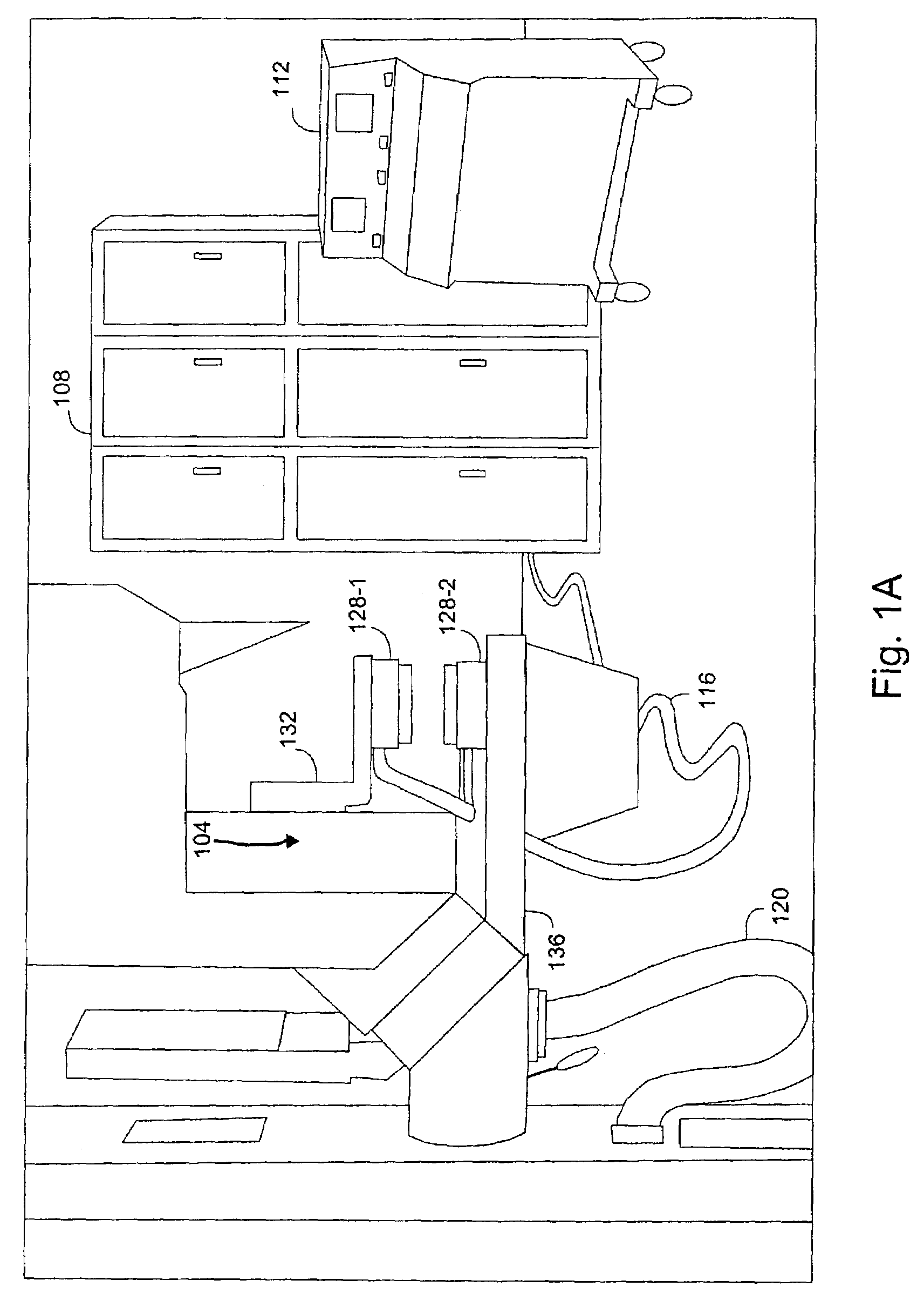
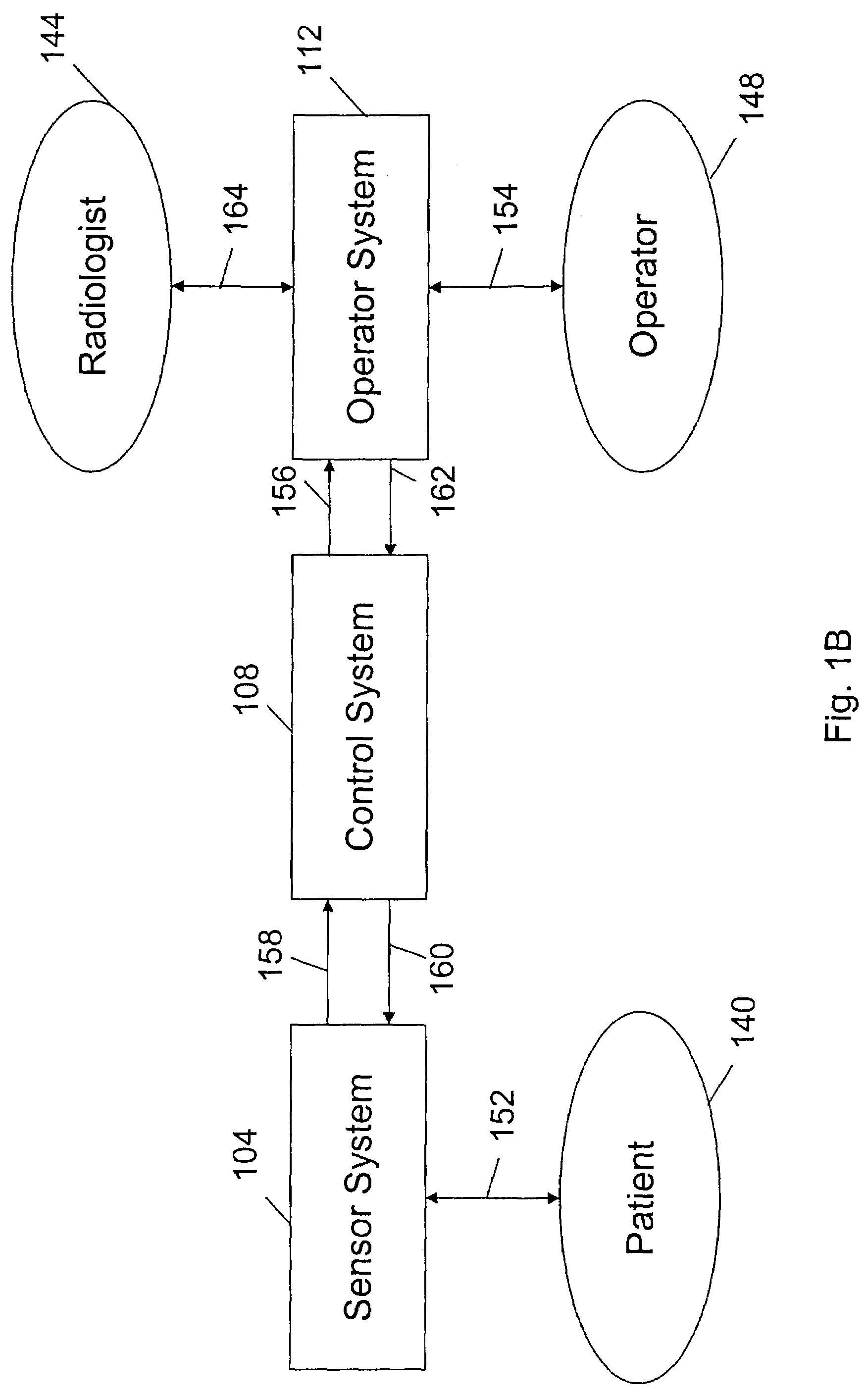
[0039]Embodiments of the invention are directed generally to a method and apparatus for examining an object under study, such as tissue. FIGS. 1A and 1B provides a general structural overview of a system that may be configured according to an embodiment of the invention appropriate for medical applications, particularly for ultrasound imaging of a patient's breast. While FIG. 1A shows the physical arrangement of the system components, FIG. 1B shows the logical interconnection of those components and how individuals interact with the system.

[0040]The system includes a sensor system 104, a control system 108, and an operator system 112. Each of these systems is described in greater detail below. A connection 116 is provided for the transfer of information between the sensor system 104 and the control system 108 and a connection (not shown in FIG. 1A) is provided for the transfer of information between the control system 108 and the operator system 112. In some embodiments, ...


PUM


Abstract

A method and system for examining tissue are provided in which the tissue is maintained in a position so that it may be insonified with a plurality of pulsed spherical or cylindrical acoustic waves. The insonifying acoustic waves are scattered by the tissue so that scattered acoustic radiation including a mix of reflected and transmitted acoustic waves is received. A representation of a portion of the tissue is then derived from the received scattered acoustic radiation.

Description

STATEMENT AS TO RIGHTS TO INVENTIONS MADE UNDER FEDERALLY SPONSORED RESEARCH OR DEVELOPMENT[0001]The Government has rights in this invention pursuant to U.S. Dept. of Energy Work for Others Agreement L-8420.CROSS-REFERENCES TO RELATED APPLICATIONS[0002]This application is being filed concurrently with related U.S. Patent application Ser. No. 10 / 323,467 “DIAGNOSTIC ANALYSIS OF ULTRASOUND DATA,” by David H. Chambers et al. filed Dec. 18, 2002 and now U.S. Pat. No. 6,984,210. This application is also related to, commonly assigned U.S. Pat. No. 6,385,474 entitled “METHOD AND APPARATUS FOR HIGH-RESOLUTION DETECTION AND CHARACTERIZATION OF MEDICAL PATHOLOGIES,” filed Mar. 19, 1999 by John D. Rather et al., the entire disclosure of which is herein incorporated by reference for all purposes.BACKGROUND OF THE INVENTION[0003]The present invention relates generally to imaging systems. More particularly, the present invention relates to ultrasound imaging systems.[0004]There are a number of dis...

Claims


Application Information

Patent Timeline
Patent Type & Authority Patents(United States)
IPC IPC(8): A61B8/00A61B5/05A61B8/08A61B8/13A61B8/14G06F
CPCA61B8/13A61B8/0825
Inventor DURIC, NEBOJSALITTRUP, PETER J.HOLSAPPLE, III, EARLEBARTER, ROBERT HENRYMOORE, THOMAS LAZEVEDO, STEPHEN G.FERGUSON, SIDNEY W.
Owner DELPHINUS MEDICAL TECH
Why Eureka
Try Eureka