
Method and apparatus for detecting slow-moving targets in high-resolution sea clutter

a high-resolution, target technology, applied in the direction of measuring devices, instruments, using reradiation, etc., can solve the problems of difficult to distinguish actual targets from the surrounding sea clutter, difficult to distinguish from the background sea clutter, and conventional track-to-detect approaches do not work well either. , to achieve the effect of effective detection of slow moving targets

Inactive Publication Date: 2007-10-23
THE UNITED STATES OF AMERICA AS REPRESENTED BY THE SECRETARY OF THE NAVY
View PDF10 Cites 17 Cited by
  • Summary
  • Abstract
  • Description
  • Claims
  • Application Information

AI Technical Summary

Benefits of technology

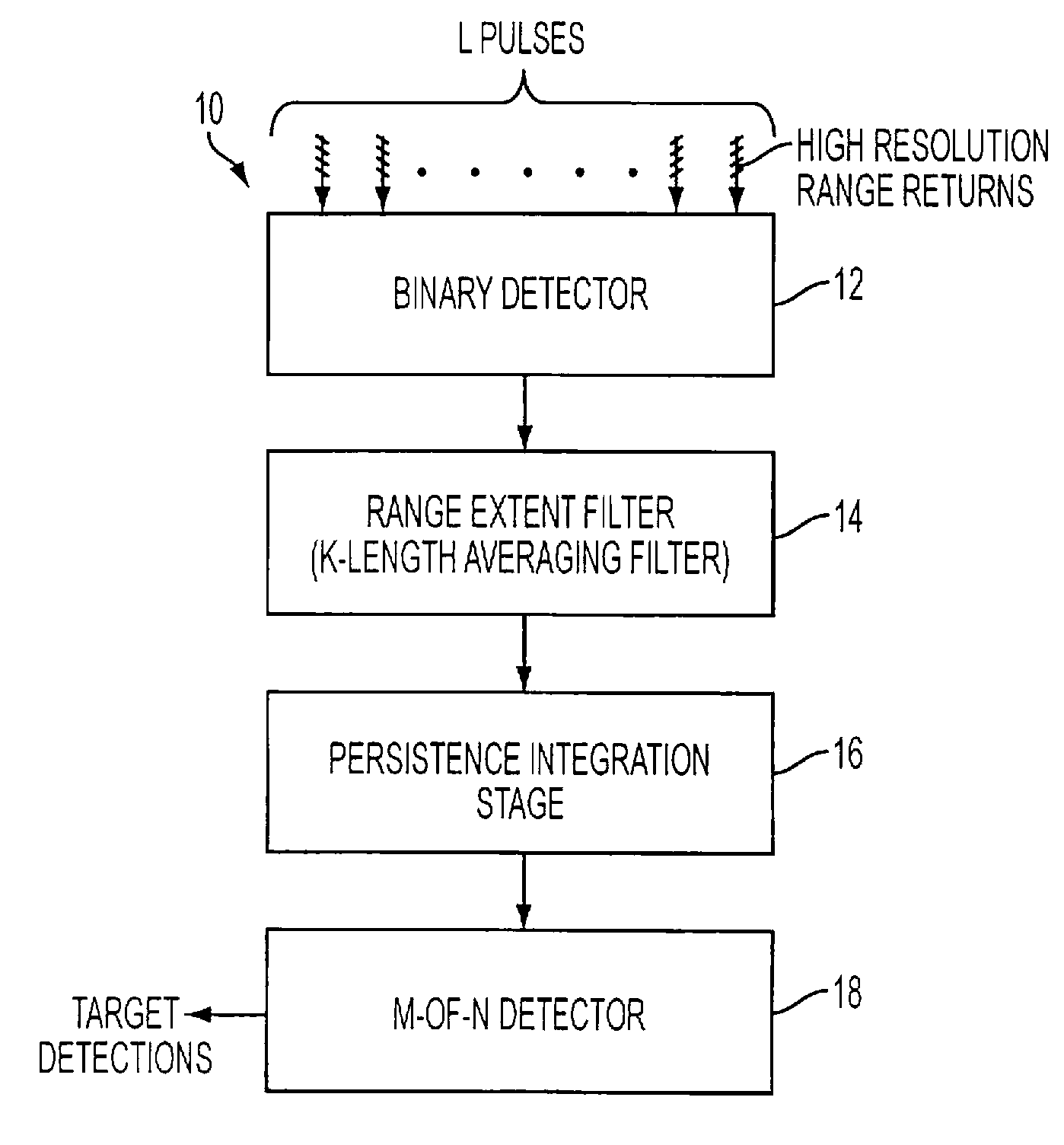
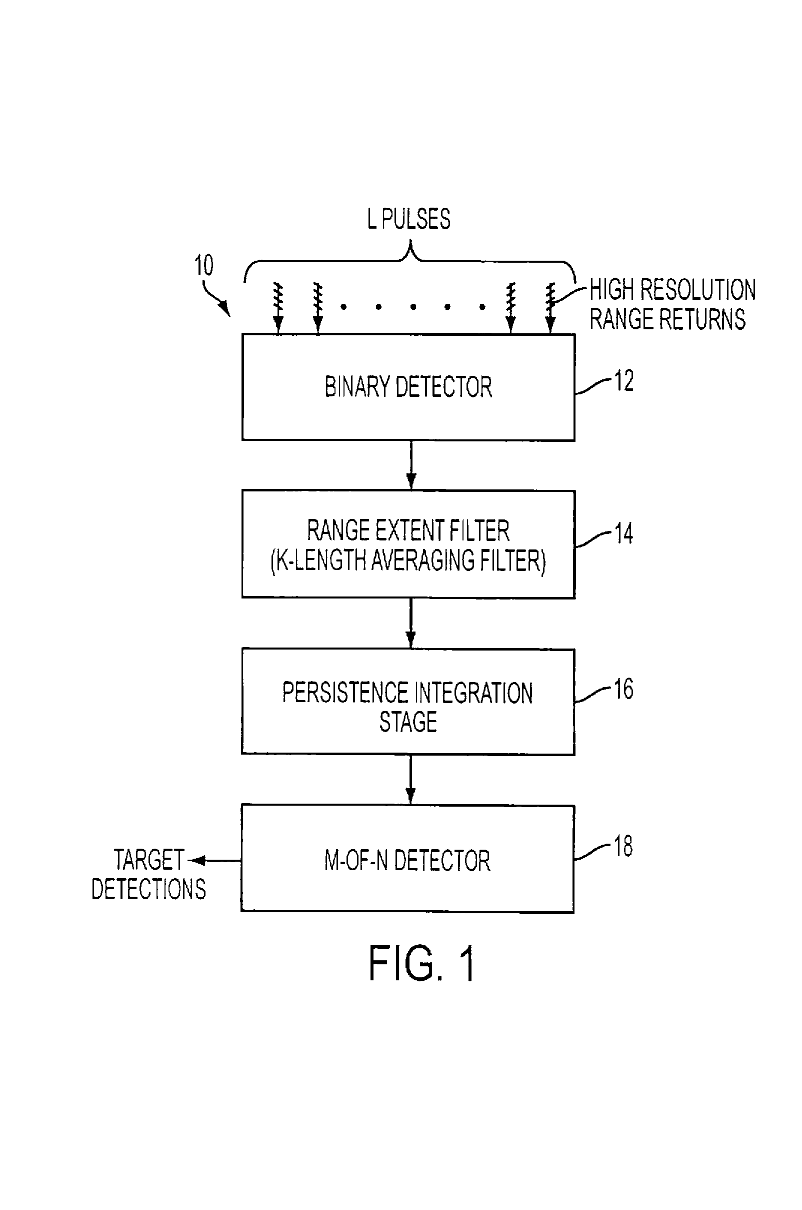
The present invention provides a method and apparatus for detecting slow-moving targets in high resolution clutter. The method involves using a binary detector to convert high resolution returns into binary outputs based on a detector threshold, a range extent filter to produce a target range extent output, a persistence integration stage to produce a persistence output based on target range extent persistence over a predetermined time period, and a detector stage to receive the persistence output and produce an output indicative of target presence. The apparatus includes a binary detector, a range extent filter, a persistence integration stage, and a detector. The technical effects of the invention include effective detection of slow-moving targets in high resolution clutter, despite the presence of sea clutter.

Problems solved by technology

While these approaches can be quite effective in some situations, for targets with little to no radial velocity component, it is quite difficult to differentiate actual targets from the surrounding sea clutter.
The reason for this is that a target with low radial velocity with respect to the radar platform has a Doppler frequency close to zero and hence is difficult to distinguish from the background sea clutter.
Further, from scan to scan, the target does not appear to be moving so that conventional track-to-detect approaches do no work well either.

Method used


Image

  • Method and apparatus for detecting slow-moving targets in high-resolution sea clutter
  • Method and apparatus for detecting slow-moving targets in high-resolution sea clutter
  • Method and apparatus for detecting slow-moving targets in high-resolution sea clutter

Examples


Embodiment Construction

[0033]To provide additional background before describing preferred embodiments of the invention, it is noted that for high enough range resolution, even rather small targets tend to extend over a number of range cells. For larger targets, the number of range cells the target extends over can become quite significant. Therefore, target extent can be used to discriminate true targets against sea clutter when the range resolution is high enough. Further, coherent processing is not necessary because the integration gain is now defined as the number of range cells within a local region that exceed some predetermined threshold, thereby defining the detectable extent of the target.

[0034]While range extent alone can, in general, achieve fairly good detection performance in high sea states, the range extent approach may suffer from an increase in false alarms. To make the detection more robust, the persistence of the target returns is used in conjunction with the range extent. This is done o...


PUM


Abstract

An apparatus for non-coherently detecting slow-moving targets in high resolution sea clutter includes a binary detector for converting high resolution radar returns, produced in response to a radar pulse scan of a plurality of identical pulses, into corresponding binary outputs based on a comparison of range cell magnitudes with a detector threshold. A range extent filter converts these binary outputs into an output indicating the presence or absence of a cluster of the returns that are closely spaced in range, while a third, persistence integration stage determines target range extent persistence over a predetermined time period. A detector stage declares detection of a target based on a comparison of the output of the third stage with a selected threshold.

Description

FIELD OF THE INVENTION[0001]This invention provides a method and apparatus for non-coherently detecting slow-moving targets in the presence of clutter and, in particular, for detecting slow-moving sea targets in the presence of sea clutter.BACKGROUND OF THE INVENTION[0002]The radar detection of targets in the presence of sea clutter has historically relied heavily upon the radial velocity of targets with respect to the radar platform. This detection is generally done in one of two ways. Specifically, it is done by estimating the relative target Dopplers (such as for STAP) (see J. Ward, “Space-time adaptive processing for airborne radar,”MIT Lincoln Laboratory Technical Report ESC-TR-94-109, December 1994). Further, it is also done by examining the path that a target traverses from scan to scan, otherwise known as the “track-before-detect” or “track-to-detect” approach (see B. D. Carlson, E. D. Evans, and S. L. Wilson, “Search radar detection and track with the Hough transform, Part ...

Claims


Application Information

Patent Timeline
Patent Type & Authority Patents(United States)
IPC IPC(8): G01S7/292G01S13/52G01S13/534
CPCG01S7/2927G01S7/414
Inventor BLUNT, SHANNON D.GERLACH, KARL R.
Owner THE UNITED STATES OF AMERICA AS REPRESENTED BY THE SECRETARY OF THE NAVY
Learn More