Transflective liquid crystal display

a liquid crystal display and transflective technology, applied in static indicating devices, non-linear optics, instruments, etc., can solve the problem of difficult to achieve high chromaticity, and achieve the effect of improving the viewing quality of the transflective liquid crystal display

Active Publication Date: 2007-10-23
AU OPTRONICS CORP
View PDF17 Cites 25 Cited by
  • Summary
  • Abstract
  • Description
  • Claims
  • Application Information

AI Technical Summary

Benefits of technology

[0006]The present invention provides a method and a pixel structure to improve the viewing quality of a transflective-type liquid crystal display. The pixel structure of a pixel in the liquid crystal display comprises a plurality of sub-pixel segments. Each of the sub-pixel segments comprises a transmission area and a reflection area. In the sub-pixel segment, a data line, a first gate line, a second gate line and a common line are used to control the operational voltage on the liquid crystal layer areas associated with the sub-segments. In particular, the transmission area is associated with a first charge storage capacity and the reflection area is associated with a second storage capacity. The first and second gate lines can be separately set at a first control state and a second control state. The ratio of the first charge storage capacity to the second charge storage capacity can be controlled according to the states of the gate lines.

Problems solved by technology

Due to the simplicity in the pixel structure of the conventional transflective LCD panel, high chromaticity is difficult to achieve.

Method used


Image

  • Transflective liquid crystal display
  • Transflective liquid crystal display
  • Transflective liquid crystal display

Examples


Embodiment Construction

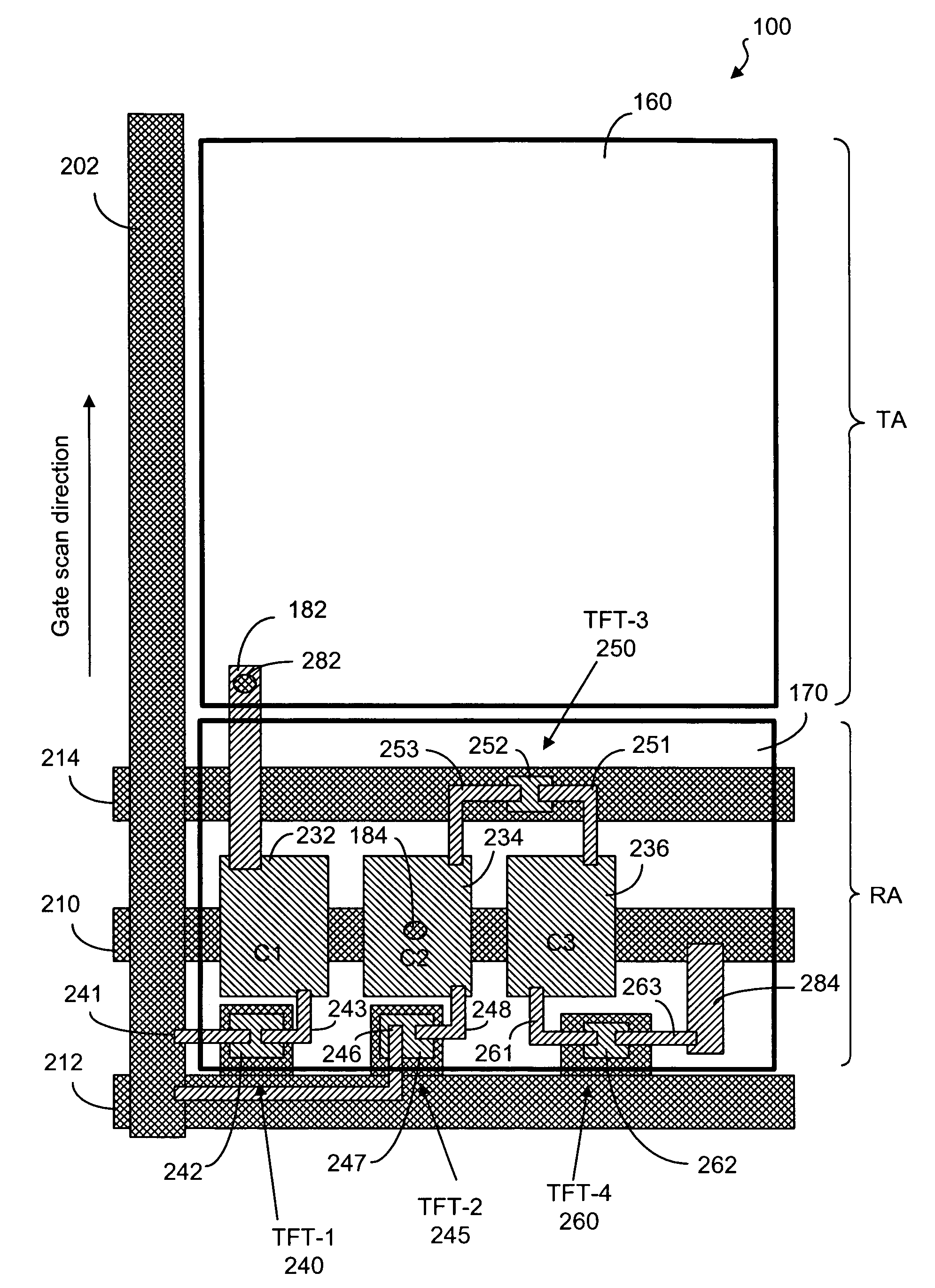
[0036]A sub-pixel segment, according to the present invention, is shown in FIG. 4. As shown, the sub-pixel segment 100 has an upper layer structure, a lower layer structure and a liquid crystal layer 190 disposed between the upper layer structure and the lower layer structure. The upper layer comprises a polarizer 120, a haft-wave plate 130, a quarter-wave plate 140 and an upper electrode 150. The upper electrode 150 is made from a substantially transparent material such as ITO (Indium-tin oxide). The lower layer structure comprises an electrode layer having a transmission electrode 160 and a reflection electrode 170. The transmission electrode 160 is made from a transparent material such as ITO. The reflection electrode 170 also serves as a reflector and is made from one or more highly reflective metals such as Al, Ag, Cr, Mo, Ti, and A1Nd. The lower layer structure further comprises a passivation layer (PL) 180, a device layer 200, a quarter-wave plate 142, a half-wave plate. 132 ...


PUM

PropertyMeasurementUnit
areaaaaaaaaaaa
voltage potentialaaaaaaaaaa
colorsaaaaaaaaaa

Abstract

A transflective liquid crystal display having a plurality of pixels, each pixel having a plurality of color sub-pixels, each sub-pixel having a transmission area associated with a first charge storage capacitance and a reflection area associated with a second storage capacitance. In the sub-pixel, a data line, a first gate line, a second gate line and a common line are used to control the operational voltage on the liquid crystal layer associated with the sub-pixel. The first and second gate lines are separately set at a first state and a second state. The ratio of the first charge storage capacitance to the second charge storage capacitance can be controlled according to the states of the gate lines. The second charge storage capacitance is provided by two capacitors connected in parallel through a switching element which can be open or closed according to the states of the gate lines.

Description

FIELD OF THE INVENTION[0001]The present invention relates generally to a liquid crystal display panel and, more particularly, to a transflective-type liquid crystal display panel.BACKGROUND OF THE INVENTION[0002]Due to the characteristics of thin profile and low power consumption, liquid crystal displays (LCDs) are widely used in electronic products, such as portable personal computers, digital cameras, projectors, and the like. Generally, LCD panels are classified into transmissive, reflective, and transflective types. A transmissive LCD panel uses a back-light module as its light source. A reflective LCD panel uses ambient light as its light source. A transflective LCD panel makes use of both the back-light source and ambient light.[0003]As known in the art, a color LCD panel 1 has a two-dimensional array of pixels 10, as shown in FIG. 1. Each of the pixels comprises a plurality of sub-pixels, usually in three primary colors of red (R), green (G) and blue (B). These RGB color comp...

Claims


Application Information

Patent Timeline
Patent Type & Authority Patents(United States)
IPC IPC(8): G02F1/136
CPCG09G3/3659G09G2300/0443G09G2320/02G09G2300/0809G09G2300/0842G09G2300/0456
Inventor LIN, CHING-HUANTSAI, CHING-YU
Owner AU OPTRONICS CORP
Why Eureka
Try Eureka