Method for designing a modal equalizer for a low frequency audible range especially for closely positioned modes

a modal equalizer and low frequency technology, applied in the direction of frequency response correction, transmission, electrical equipment, etc., can solve the problems of complex temporal behavior, difficult or impossible to find analytical or numerical models that are useful in practice, and the decomposition of eigenmodes assuming a linear and time-invariant (lti) system,

Active Publication Date: 2007-10-23
GENELEC
View PDF3 Cites 19 Cited by
  • Summary
  • Abstract
  • Description
  • Claims
  • Application Information

AI Technical Summary

Benefits of technology

[0037]The invention offers substantial benefits.
[0038]With help of the invention also modes close to each other can be equalized effectively.

Problems solved by technology

For irregular structures and / or higher frequencies it is much more difficult or impossible to find analytical or numerical models that are useful in practice.
The modal behavior, i.e., decomposition of eigenmodes assuming a linear and time-invariant (LTI) system, can be extremely complicated.
In one-dimensional resonators, such as strings and tubes in musical instruments, the density of eigenmodes is not necessarily high, but these modes can exhibit complicated details, for example two-stage decay and strong beating in a decaying envelope.
Also the temporal behavior becomes complex, especially in rooms where the direct sound and early reflections are followed by an increasing density of reflections resulting in late reverberation.

Method used


Image

  • Method for designing a modal equalizer for a low frequency audible range especially for closely positioned modes
  • Method for designing a modal equalizer for a low frequency audible range especially for closely positioned modes
  • Method for designing a modal equalizer for a low frequency audible range especially for closely positioned modes

Examples


Embodiment Construction

4 Frequency-zooming ARMA (FZ-ARMA)

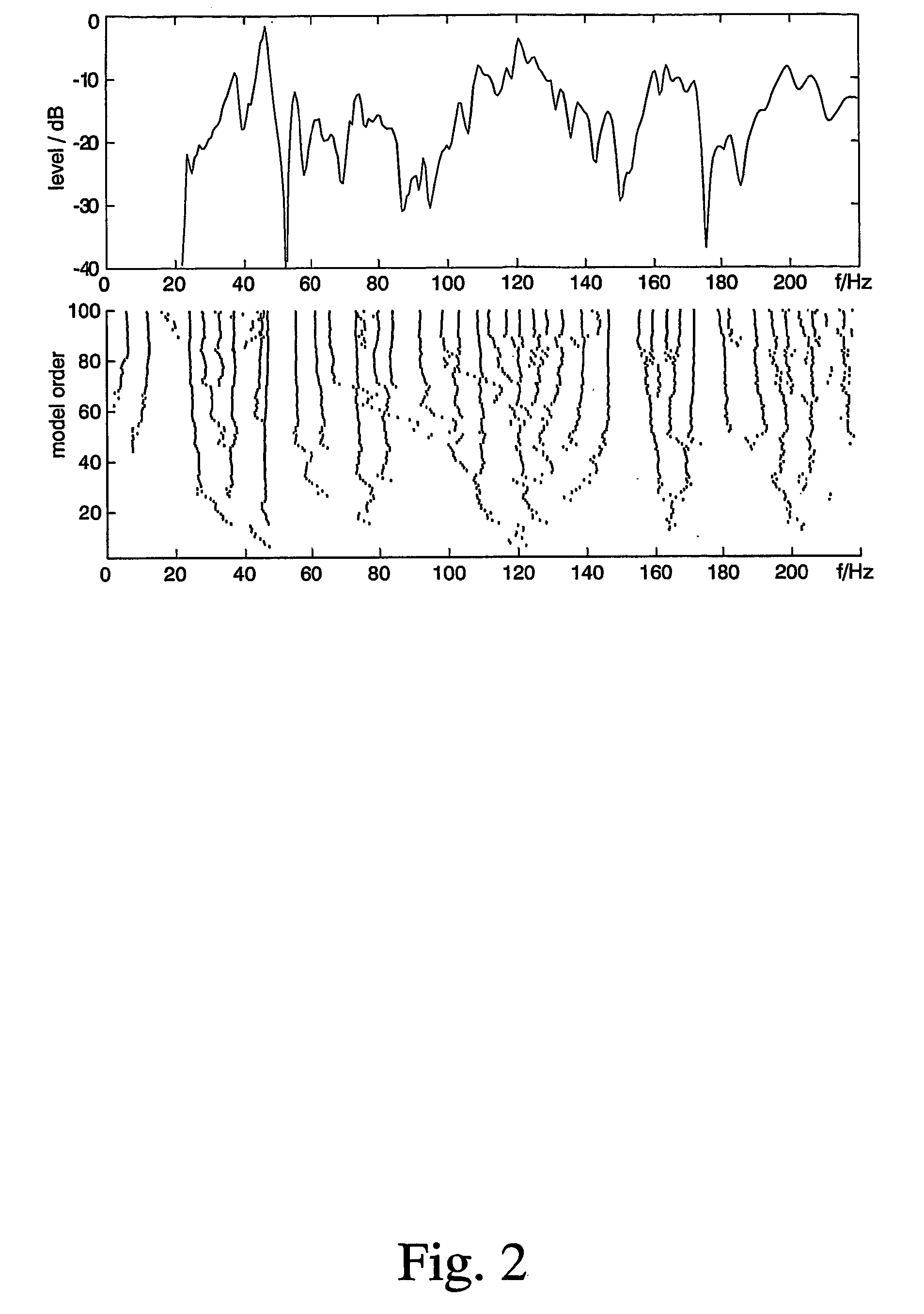
[0055]The problems in resolving very closely positioned modes and mode groups was the reason in this study to experiment with methods that have better control over frequency resolution. Several ideas are available for improvement, including frequency warping [22] and frequency selective modeling such as selective linear prediction [15], multiband AR / ARMA techniques [16], and many other high-resolution signal modeling methods.

[0056]Frequency warping is a convenient technique when either lowest or highest frequencies require enhanced frequency resolution. This approach can be extended to Kautz filters that exhibit interesting properties of generalized frequency resolution control [23].

[0057]Frequency selective modeling has been applied for example in linear prediction of speech. In a simple case a target response can be low-pass filtered and decimated in order to model the low-frequency part of the response. A range of higher frequencies can be modula...


PUM


Abstract

The present invention relates to a method for designing a modal equalizer (5) for a low frequency audible range, typically for frequencies below 200 Hz for a predetermined space (1) (listening room) and location (2) (location in the room) therein, in which method modes to be equalized are determined at least by center frequency and decay rate of each mode, creating a discrete-time description of the determined modes, and determining equalizer filter coefficients on the basis of the discrete-time description of the determined modes, and forming the equalizer (5) by means of a digital filter by defining the filter coefficients on the basis of the properties of the modes. In accordance with the invention following method steps are used: forming a mode detection function (G(Ω)), defining the highest peak angular frequency Ωp of the function (G(Ω)), making AR analysis of predefined order for solving the poles of the mode representing the highest peak angular frequency, selecting the pole closest to point ejΩp on the unit circle, determining the decay time of the mode and if is over a predetermined level, designing a modal correction filter for this mode, and repeating this procedure until no decay time exceeds over the predetermined level, and each individual filter obtained in previous stages of the method is combined to a cascaded filter.

Description

BACKGROUND OF THE INVENTIONField of the Invention[0001]The invention relates to a method for designing a modal equalizer for a low frequency audible range especially for closely positioned modes.SUMMARY AND OBJECTS OF THE INVENTION[0002]Parametric analysis and modeling is an increasingly common task in acoustics and audio. In this invention we focus on such audio related problems where a target system response can be measured and the task is to model it for computational simulation / synthesis or to inverse model it for equalization, i.e., compensation for nonidealities in the observed response. Representative examples of the first group, forward simulation for synthesis, are room response modeling including artificial reverb design, or just estimation of eigenmodes at low frequencies in room acoustical studies, and modeling of musical instruments. The second category, the inverse modeling is common in audio, where equalization of non-ideal response properties is a frequent task in hi...

Claims


Application Information

Patent Timeline
Patent Type & Authority Patents(United States)
IPC IPC(8): H04B3/20H03G5/16H04R3/04
CPCH04R3/04H03G5/165
Inventor KARJALAINEN, MATTIANTSALO, POJUVALIMAKI, VESAMAKIVIRTA, AKI
Owner GENELEC
Why Eureka
Try Eureka