
Data transfer apparatus and data transfer method

Inactive Publication Date: 2007-10-23
NEC CORP
View PDF28 Cites 14 Cited by
  • Summary
  • Abstract
  • Description
  • Claims
  • Application Information

AI Technical Summary

Benefits of technology

[0018]The present invention has its object to provide data transfer apparatus and data transfer method for determining priorities of data frame transmission among plural queues easily and efficiently, while insuring minimum guaranteed rates defined for the respective queues.
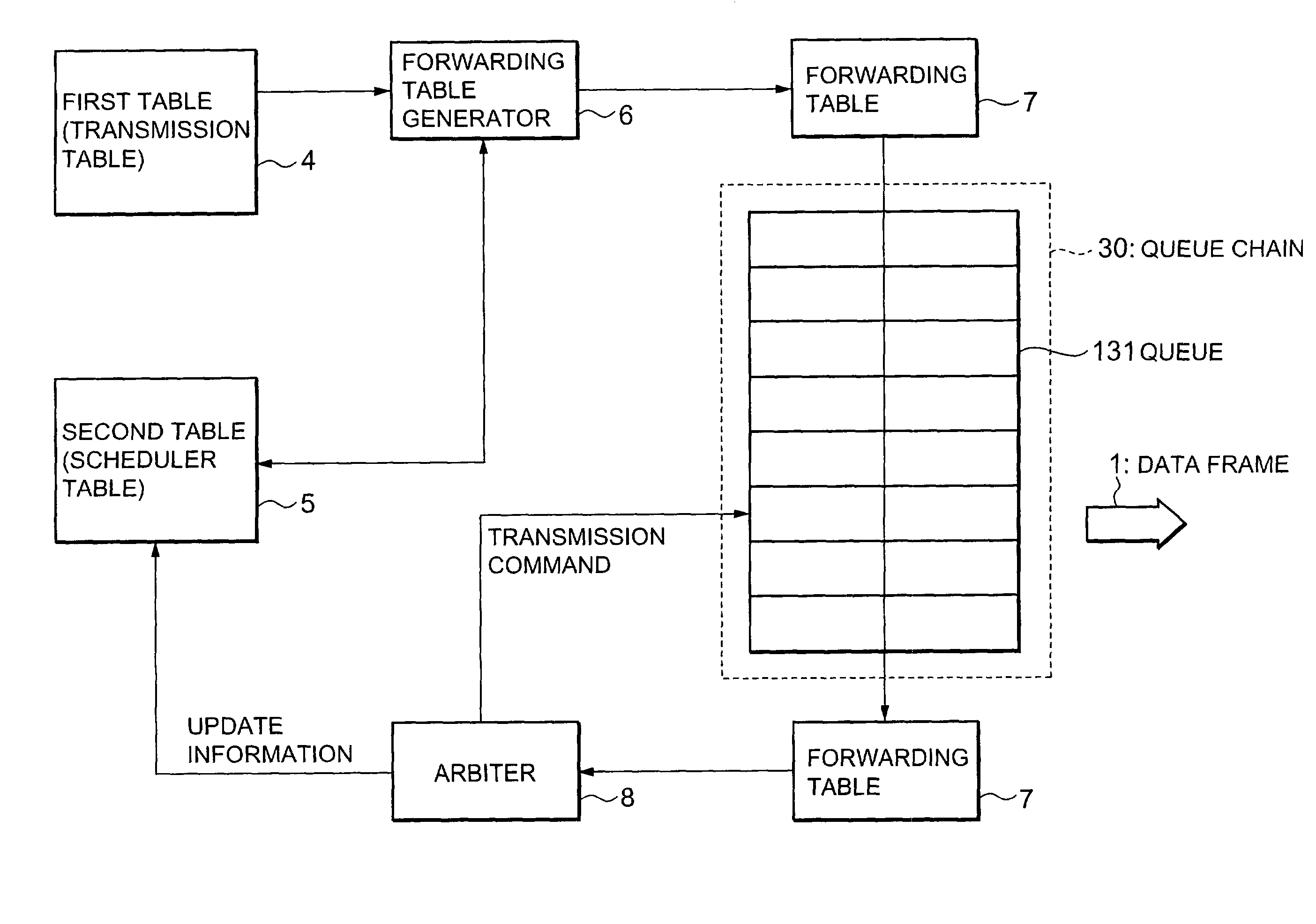
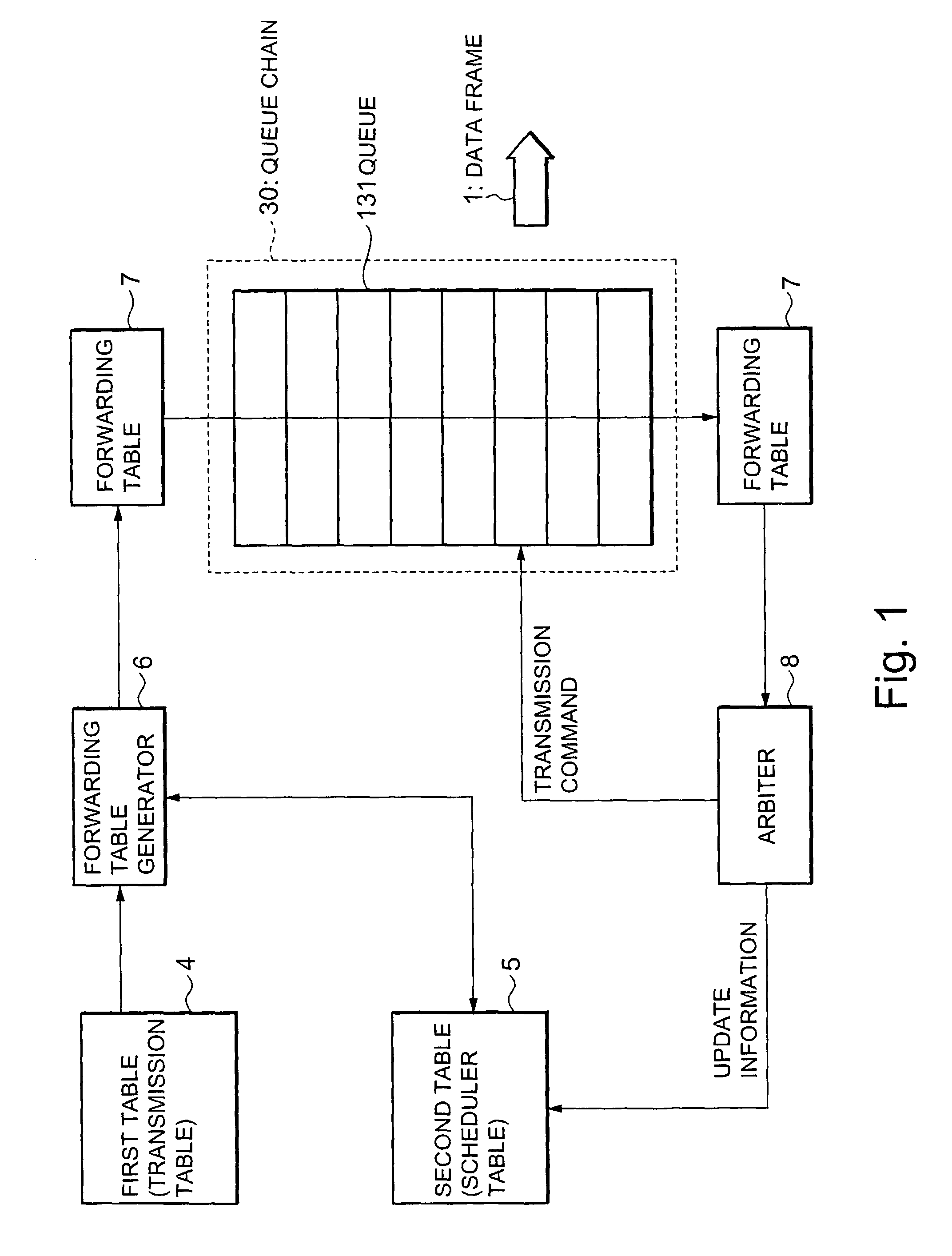
[0023]Further, a function for determining the priorities is realized by an arbiter 8, it is not necessary to provide plural round robin function blocks. Accordingly, it is not necessary to reconstruct a queue group to which each round robin belongs in correspondence with change of queue usage. As a result, processing can be performed easily in correspondence with various combinations of queue usages.

Problems solved by technology

However, in the above-described conventional 2-step shaping, the following three problems occur upon determination of priorities of data frame transmission among the respective queues 131.
The first problem is that it is necessary to reconstruct a queue group to which each round robin belongs in correspondence with change of combination of traffic shaping, and processing is complicated.
The second problem is that if the minimum guaranteed rate and priority are set for each queue 131, it is necessary to prepare a queue corresponding to the settings or a queue having all the settings for selection of function.
In this case, processing is also complicated.
Further, the third problem is that in the conventional circuit, in a case where the minimum guaranteed rate and priority can be set for each queue and round robin, the circuit scale increases.
Thus the number of queues cannot be increased without difficulty.

Method used


Image

  • Data transfer apparatus and data transfer method
  • Data transfer apparatus and data transfer method
  • Data transfer apparatus and data transfer method

Examples


Embodiment Construction

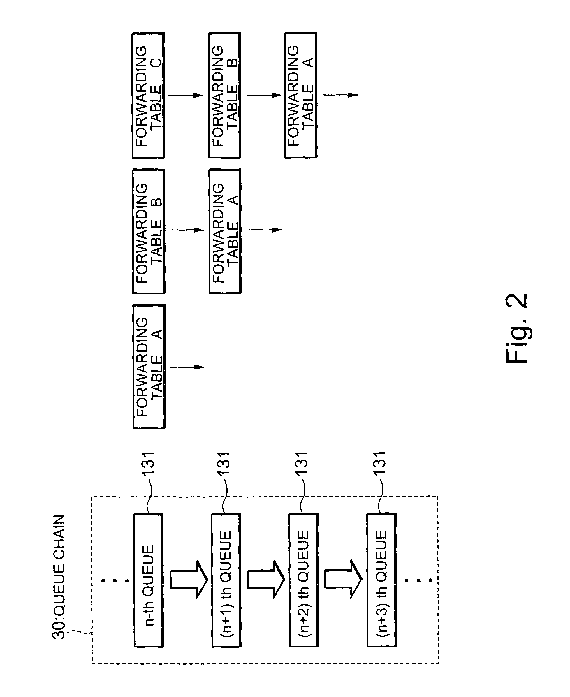
[0039]A preferred embodiment of data transfer apparatus and data transfer method of the present invention will be described in accordance with FIGS. 1 to 12.

[0040]Note that priority determination processing in data transfer in the following embodiment is executed by a computer controlled by a program. The program is provided from e.g. a recording medium. As the recording medium, a magnetic disk, a semiconductor memory or other arbitrary computer-readable medium can be used. Further, the program recorded in the recording medium can be read by the computer via a communication line.

[0041]The construction of the data transfer apparatus of the present embodiment is basically the same as that of the conventional data exchange unit 100 shown in FIG. 11. The present data transfer apparatus has plural queues (output buffer queues) 131 for temporarily storing data frames. Further, as shown in FIGS. 12 and 13, the queues 131 are divided into M (M is an integer equal to or greater than 2) sched...


PUM


Abstract

A forwarding table 7 where a next transmission queue is registered is sequentially transferred within a queue chain 30 as a group of queues 131. If a priority of a queue to which the forwarding table 7 is transferred is higher than that of a queue registered in the forwarding table 7 as a next transmission queue, a next transmission queue number or the like is updated. Further, an arbiter 8 outputs a transmission command to a queue registered as the next transmission queue in the forwarding table 7 which has been transferred through all the queues, to transmit the next data frame from the queue having the highest priority. By this arrangement, it is possible to determine data frame transmission priorities among plural queues easily and efficiently while insuring a minimum guaranteed rate defined in each queue.

Description

BACKGROUND OF THE INVENTION[0001]1. Field of the Invention[0002]The present invention relates to a data transfer technique in communication apparatuses and the like, and more particularly, to data transfer apparatus and data transfer method for determining transmission priorities of data frames transmitted from plural queues.[0003]2. Description of Related Art[0004]First, a general construction of data exchange unit utilized in ATM communication or the like will be described with reference to FIG. 11.[0005]As shown in FIG. 11, a data exchange unit 100 comprises plural input buffer cards 110, a switch core 120 and plural output buffer cards 130.[0006]A data frame received by the data exchange unit 100 is passed through an input buffer queue 111 of the input buffer card 110, then switched by the switch core 120, and sent to any one of the output buffer cards 130. Each output buffer card 130 has plural output buffer queues (hereinbelow simply referred to as “queues”) 131. The data fram...

Claims


Application Information

Patent Timeline
IPC IPC(8): G06F15/16H04L47/22H04L47/6275
CPCH04L12/5693H04L47/6225H04L47/2441H04L47/22H04L47/50
Inventor TSUBOTA, KEISUKE
Owner NEC CORP
Learn More