Adaptive predistortion linearized amplifier system employing selective sampling

a linearized amplifier and predistortion technology, applied in amplifiers, amplifier modifications to reduce noise influence, electrical equipment, etc., can solve problems such as corrupting the search process for optimal tuning parameters, unreliable differential log measurements, and undesirable gain of power amplifiers

Active Publication Date: 2007-10-30
INTEL CORP
View PDF11 Cites 36 Cited by
  • Summary
  • Abstract
  • Description
  • Claims
  • Application Information

AI Technical Summary

Benefits of technology

[0006]In a first aspect the present invention provides an adaptive predistortion linearized amplifier system comprising an input receiving an input signal, a predistorter coupled to the input and performing a predistortion operation on the input signal using predistortion coefficients and providing a predistorted input signal, a power amplifier receiving and amplifying the predistorted input signal and providing an amplified signal, an output coupled to the power amplifier and providing the amplified signal as an output signal and an adaptation circuit coupled to the input and output and receiving sampled input and output signals therefrom. The adaptation circuit comprises a selective sampling circuit providing a reduced number of samples derived from the sampled input and output signals using a signal characteristic related to the input signal magnitude and an estimator coupled to the selective sampling circuit and performing an adaptation operation using the reduced number samples to determine updated predistortion coefficients. The adaptation circuit is coupled to the predistorter and provides the updated predistortion coefficients to the predistorter.
[0007]In a preferred embodiment of the adaptive predistortion linearized amplifier system the adaptation circuit further comprises an envelope detector coupled to receive the sampled input signal. The signal characteristic related to the input signal magnitude may comprise the sampled input signal envelope and the selective sampling circuit selects local peaks of the envelope. Alternatively, the signal characteristic related to the input signal magnitude may comprise the rate of change of the sampled input signal envelope. More specifically the signal characteristic may comprise the ratio of the rate of change of the sampled input signal envelope to the magnitude of the signal envelope. The reduced number of samples provided to the estimator preferably comprises a set of sample triples, each triple comprising a sample related to the difference in log magnitude between the sampled input signal and sampled output signal, a sample related to the difference in phase between the sampled input signal and the sampled output signal, and the sampled input signal envelope. Alternatively, the reduced number of samples provided to the estimator may comprise a set of sample triples, each triple comprising a sampled input signal, a time aligned sampled output signal, and a time aligned sampled input signal envelope. The input signal may be an analog RF modulated signal and the predistorter performs an analog predistortion operation on the input signal. Alternatively, the input signal may be a digital baseband signal and the predistorter performs a digital predistortion operation on the input signal, and the amplifier system further comprises a digital to analog converter and up converter circuit coupled between the predistorter and the power amplifier. The adaptation circuit may comprise a differential log detector coupled to receive time aligned samples of the sampled input signal and sampled output signal and providing a sampled log magnitude difference signal related to the difference in log magnitude of the sampled input signal and sampled output signal and a sampled phase difference signal related to the difference in phase between the sampled input signal and sampled output signal. The sampled input signal envelope and the output of the differential log detector are provided to the selective sampling circuit. Alternatively, the output of the selective sampling circuit is provided to the differential log detector and the differential log detector operates on a reduced set of sampled input signals and sampled output signals.
[0008]According to another aspect the present invention provides a method for adaptive predistortion of an amplifier system having an input, an output and a power amplifier. The method comprises receiving an input signal at the input of the amplifier system, predistorting the input signal using predistortion coefficients, amplifying the predistorted input signal and providing the amplified signal to the output as an output signal. The method further comprises sampling the input signal to provide input signal samples, and sampling the output signal to provide output signal samples. The method further comprises reducing the number of input and output samples using a characteristic of the input signal related to the input signal magnitude and adaptively adjusting the predistortion coefficients using the reduced number of samples.
[0009]In a preferred embodiment of the method, reducing the number of input and output samples may comprise detecting the envelope of the input signal and selecting input samples having an envelope value which is the peak value within a group of samples. The envelope values corresponding to the selected samples may be used along with the selected samples for adaptively adjusting the predistortion coefficients. Alternatively, reducing the number of input and output samples may comprise selecting input samples having a rate of change of envelope value below a first threshold and an envelope value above a second threshold.

Problems solved by technology

Nonlinearities in the gain of a power amplifier are considered undesirable because intermodulation distortion (IMD) is generated for input signal formats with varying amplitude.
Unfortunately, the differential log measurements are not reliable because outlier measurements with large errors are possible.
Such outlier measurements corrupt the search process for the optimal tuning parameters.

Method used


Image

  • Adaptive predistortion linearized amplifier system employing selective sampling
  • Adaptive predistortion linearized amplifier system employing selective sampling
  • Adaptive predistortion linearized amplifier system employing selective sampling

Examples


first embodiment

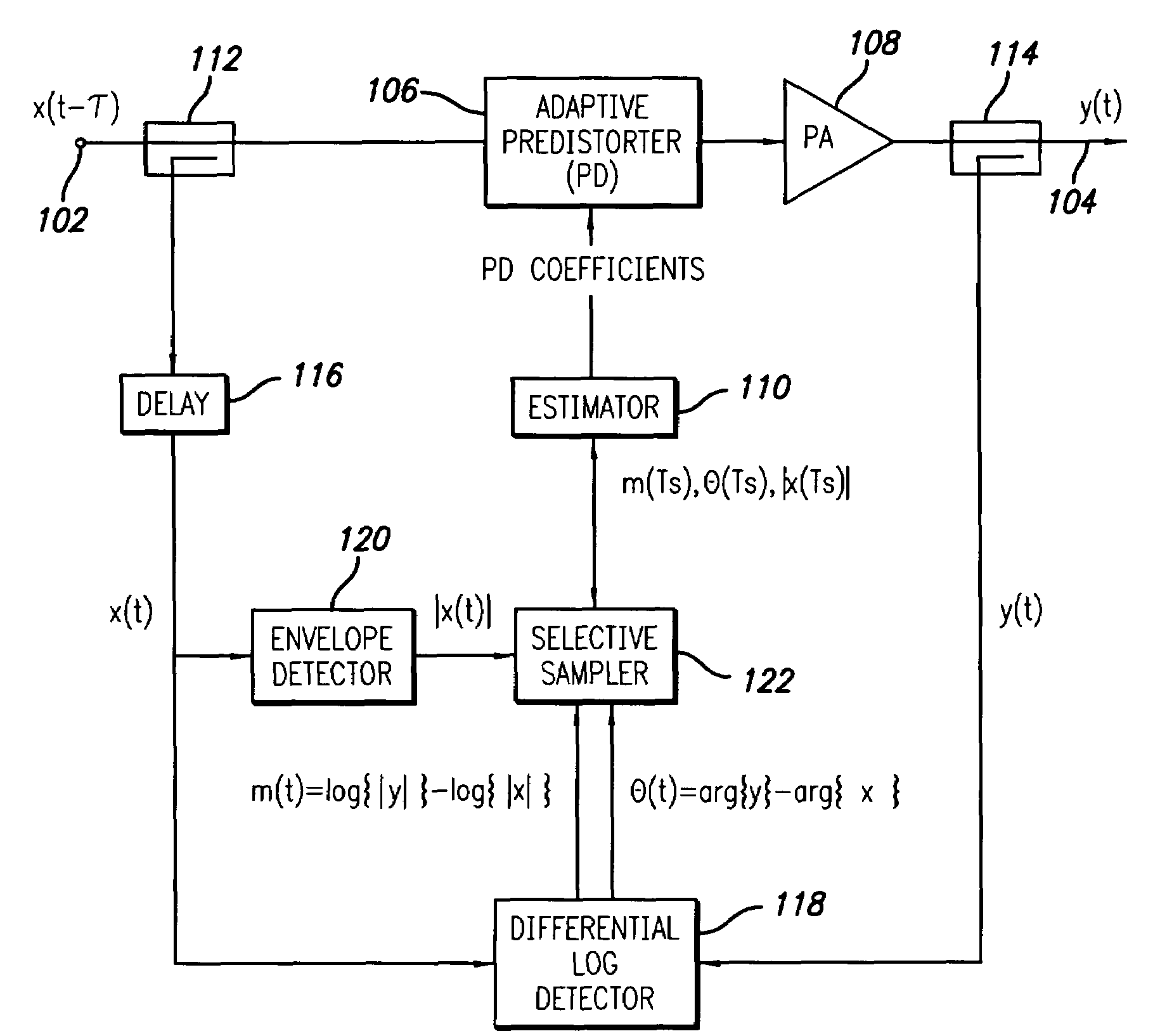
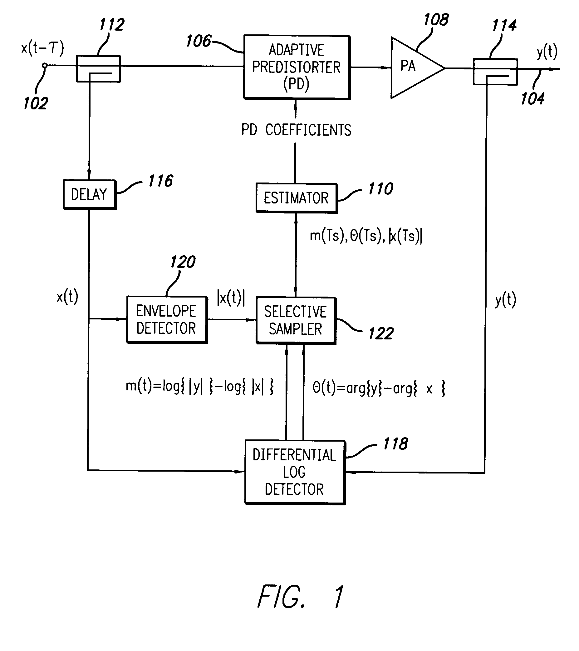
[0073]More specifically, referring to FIG. 7 an implementation of the selective sampling circuit with an analog input is shown. This implementation may be employed for circuit 122 of FIG. 1 and the input signals may be time aligned analog signals (m, θ, |x|) as described therein. The analog input signals are converted to discrete samples at analog sampling circuit 702 which outputs digital samples for time aligned triples (m, θ, |x|). These are provided to respective to temporary storage locations 704, 706, 708 which each store N samples. The N envelope samples are compared at envelope magnitude selection circuit 710 which selects the peak envelope sample from the N stored samples. Circuit 712 checks if the selected sample is an endpoint and if not the sample is selected as valid. If valid the sample number is output to magnitude and phase sample selection circuits 714, 716, respectively, which output the corresponding magnitude and phase samples. The circuit of FIG. 7 may be implem...

embodiment 1

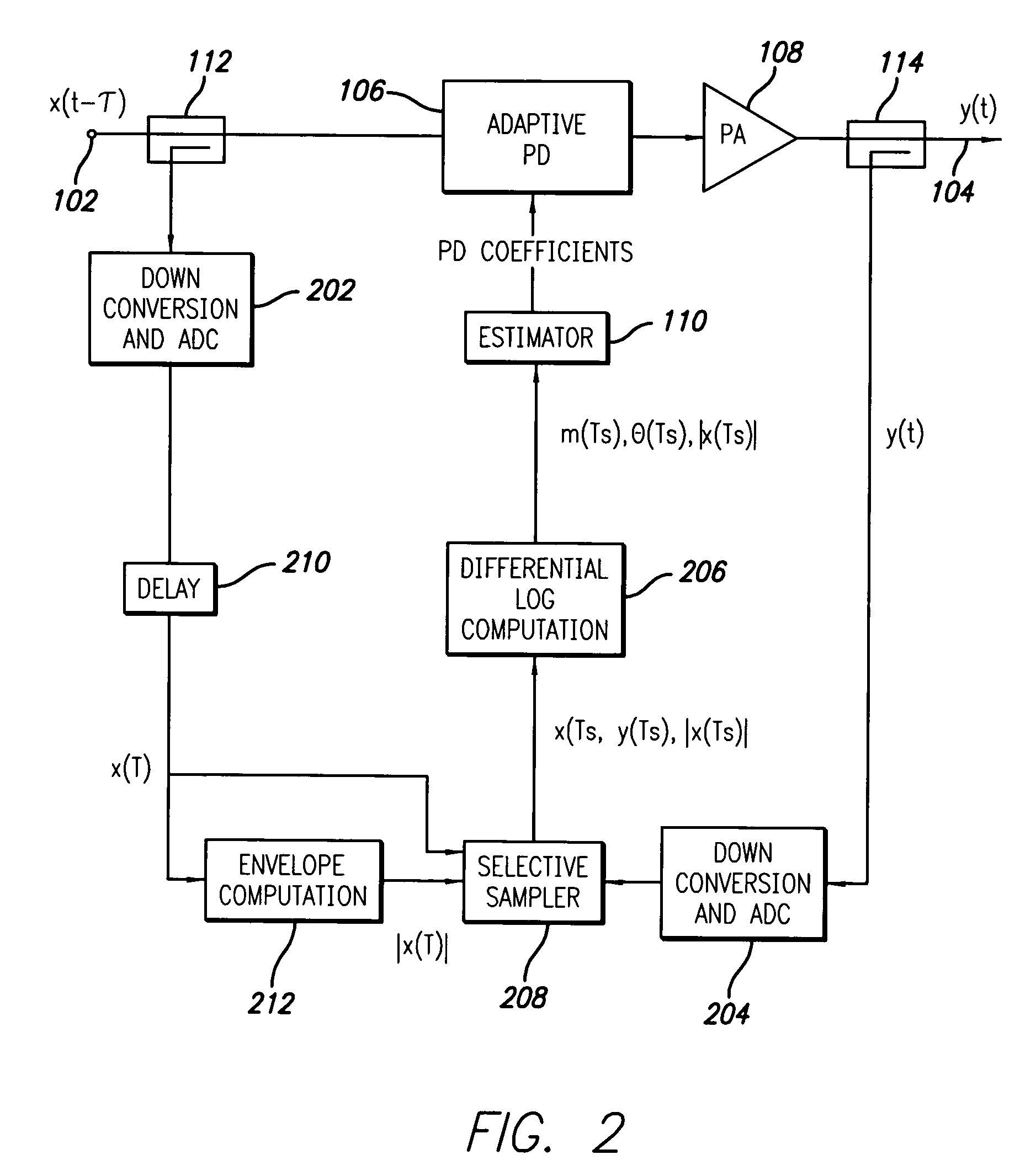
[0074]The implementation of the selective sampling circuit of FIG. 8 corresponds to embodiment 1 operating on digital samples, time aligned triples, as inputs. This implementation may be employed for the systems of FIGS. 2-6 and the circuit receives time aligned triples (m, θ, |x|) or (x, y, |x|) depending of the embodiment. The operation of the circuit corresponds to that of FIG. 7 after sampling circuit 702 and circuit blocks 804, 806, 808, 810, 812, 814 and 816 operate in the same manner as circuit blocks 704, 706, 708, 710, 712, 714 and 716 described above to select samples that are local peaks.

[0075]The second approach measures the ratio of the derivative of the input envelope and instantaneous input envelope:

[0076]∂xx,(Eq.⁢27)

where δ|x| is approximated, typically, by the difference between neighboring samples. The criteria for a valid sample becomes

∂|x|<η1·|x| and |x|>η2·E[|x|],  (Eq. 28)

second embodiment

where η1 and η2 are thresholds (typical value for η2 is 0.3). The first threshold limits the input derivative of selected samples; the second threshold rejects samples obtained from low input levels. The optimal value of η1 depends, in part, on the technique used to measure of the derivative δ|x|. It requires normalization if the sampling rate is altered or if the estimates are obtained using a high pass filter. In general, a smaller value of η1 should be selected if the time-alignment between the input and output signals entering the differential log detector is imprecise or the memory within the power amplifier is not small. With the appropriate adjustments to the thresholds, η1 and η2, selective sampling can be based on the input power or log power instead of the input envelope. The block diagrams of two implementations of the selective sampler are shown in FIGS. 9 and 10.

[0077]More specifically, referring to FIG. 9 an implementation of the second embodiment of the selective samp...


PUM


Abstract

An adaptive predistortion linearized amplifier system employing selective sampling is disclosed. Two selective sampling methods of identifying valid measurements using information from the input signal are disclosed. The selective sampling process improves the convergence properties of tuning algorithms based on minimizing the gain error variance. It also reduces the number of data samples processed by the estimator used in the tuning process.

Description

RELATED APPLICATION INFORMATION[0001]The present application claims priority under 35 USC 119(e) to provisional patent application Ser. No. 60 / 670,907, filed Apr. 13, 2005, the disclosure of which is incorporated herein by reference in its entirety.FIELD OF THE INVENTION[0002]The present invention relates to predistortion linearized amplifier systems and related methods. More particularly, the present invention relates to adaptive predistortion systems and methods.BACKGROUND OF THE INVENTION[0003]Nonlinearities in the gain of a power amplifier are considered undesirable because intermodulation distortion (IMD) is generated for input signal formats with varying amplitude. Predistortion is a method of compensating for a power amplifier with nonlinear gain by producing an inverse gain in an attempt to make the combined gain linear. When the system is linear, the overall gain is constant for any input power level. The variance of the gain over the range of input power levels is a measur...

Claims


Application Information

Patent Timeline
Patent Type & Authority Patents(United States)
IPC IPC(8): H03F1/26
CPCH03F1/3247H03F1/3258H03F1/3282H03F2201/3227H03F2200/195H03F2200/207H03F2200/435H03F2200/102
Inventor BRAITHWAITE, RICHARD NEIL
Owner INTEL CORP
Why Eureka
Try Eureka