Endoscope reader

a technology of endoscope and reader, which is applied in the field of endoscopic video camera systems, can solve the problems of ineffective assuring the level of scrutiny required for medical equipment, laborious and inaccurate simple inventory control and sign-out sheets, and inability to use unauthorized repair services in medical facilities

Active Publication Date: 2007-10-30
KARL STORZ IMAGING INC
View PDF17 Cites 833 Cited by
  • Summary
  • Abstract
  • Description
  • Claims
  • Application Information

AI Technical Summary

Benefits of technology

[0022]In yet another advantageous embodiment of the present invention, an endoscopic video system is provided for automatically adjusting to the parameters of a plurality of endoscopes, and to provide for the transfer of modified endoscope use history data comprising: a transponder / transceiver affixed to a camera head, set to transmit radio frequency signals containing electronic representations of the modified endoscope use history data, and set to receive radio frequency signals containing electronic representations of endoscope parameters and endoscope use history data; and a camera control unit, coupled to the camera head, for receiving and processing the electronic representations of endoscope parameters and endoscope use history data.
[0023]In still another advantageous embodiment of the present invention, a method is provided for communicating endoscope parameters and use characteristics from an endoscope, having a memory device and a first transponder / transceiver coupled to the memory device, to a camera control unit, and communicating modified endoscope use characteristics from the camera control unit to the endoscope comprising the steps of: storing a plurality of endoscope parameters and endoscope use characteristics in the memory device; providing a camera head with a second transponder / transceiver; coupling the second transponder / transceiver to the camera control unit; retrieving the endoscope parameters and endoscope use characteristics from the memory device; transmitting a first radio frequency signal containing the endoscope parameters and endoscope use characteristics from the first transponder / transceiver; receiving the first radio frequency signal at the second transponder / transceiver; transferring the endoscope parameters and endoscope use characteristics contained in the first radio frequency signal from the camera head to the camera control unit; transferring modified endoscope use characteristics from the camera control unit to the camera head; transmitting a second radio frequency signal containing the modified endoscope use characteristics from the second transponder / transceiver to the first transponder / transceiver; receiving the second radio frequency signal containing the modified endoscope use characteristics; and storing the modified endoscope use characteristics in the memory device memory locations.

Problems solved by technology

From a manufacturer's perspective, it is important that only factory authorized personnel service their products; however, it is a reality in the marketplace that some medical facilities may use unauthorized repair services.
Rather, both the '166 and the '868 patents are limited to updating only the camera unit.
Another problem in the field of endoscope management is that of keeping track of the many different endoscopes used throughout the facility.
Simple inventory control and sign-out sheets are labor intensive and inaccurate, and, as a result, are ineffective for assuring the level of scrutiny that is required for medical equipment.
Further, sign-out sheets do not allow for monitoring equipment, for example, determining whether the endoscope is functioning properly or needs maintenance.
However, bar coding is ineffective when the equipment has been moved since the last time that it was scanned.
Moreover, the use of bar codes can require the labor-intensive step of touring the facility with one or more portable scanners in search of endoscopes.
Further, bar codes, like sign-out sheets, do not allow for the monitoring of equipment, for example, determining whether the endoscope is functioning properly or needs maintenance.
One major problem with the use of inductive coupling as disclosed in the '722 patent is that it can create unacceptable levels of electromagnetic interference (“EMI”) in the operating room environment.
Electronic equipment, such as the video signals transmitted from the camera head to the camera control unit, can be particularly sensitive to EMI.
This, however, significantly adds to the cost and manufacturing time of the device.
Therefore, a system that does not produce EMI is greatly desired.
Another disadvantage with the use of inductive coupling as disclosed in the '722 patent is that it necessitates the use of inductive coils both in the endoscope and the camera head adding greatly to the size and the weight of the devices.
In addition to the added size and weight of the inductive coils, the necessary shielding for the EMI produced by the inductive coils will further increase the device size and weight.
Another disadvantage to the inductive coupling technique as disclosed in the '722 patent is because high frequency coils act like a loosely coupled transformer, both high frequency coils should be aligned one directly on top of the other in order to achieve an effective data transfer.
This situation could be very frustrating for medical professionals, having to spend time trying to accurately align the camera head and endoscope to have the video system function properly.
However, RFID used in the operating room environment has been limited due to the large power ranges required for locating the device.
A large power range, unfortunately, may cause receipt of the signal by unintended RFID receivers.
That is, if an endoscope is in use in room A, it is undesirable to have unrelated endoscope equipment in room B “respond” to the transceiver.
RFID has been limited to tracking the location of devices and / or equipment, facilitating only one-way communication from the device and / or equipment to the recording or tracking system.

Method used


Image

  • Endoscope reader
  • Endoscope reader
  • Endoscope reader

Examples


Embodiment Construction

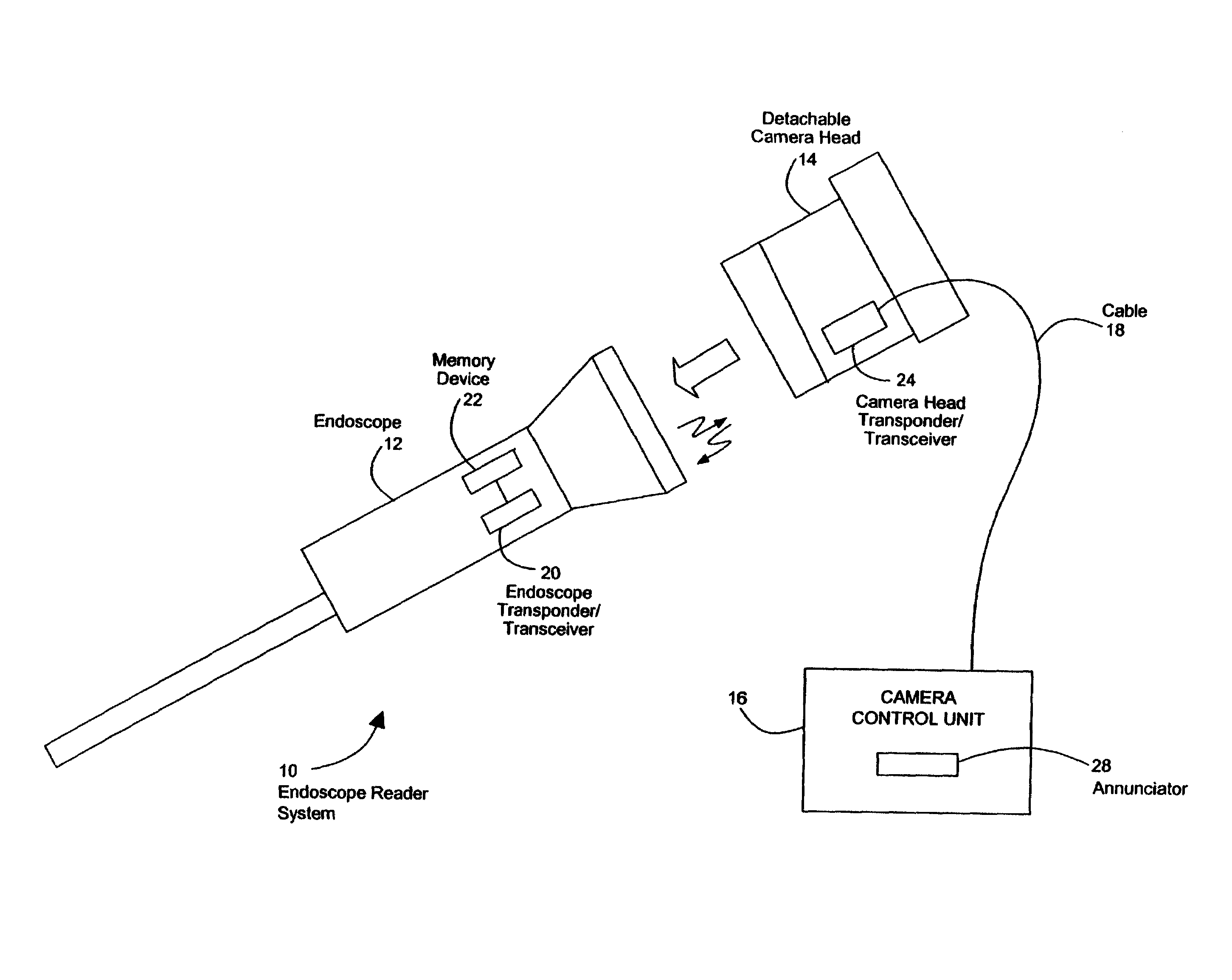
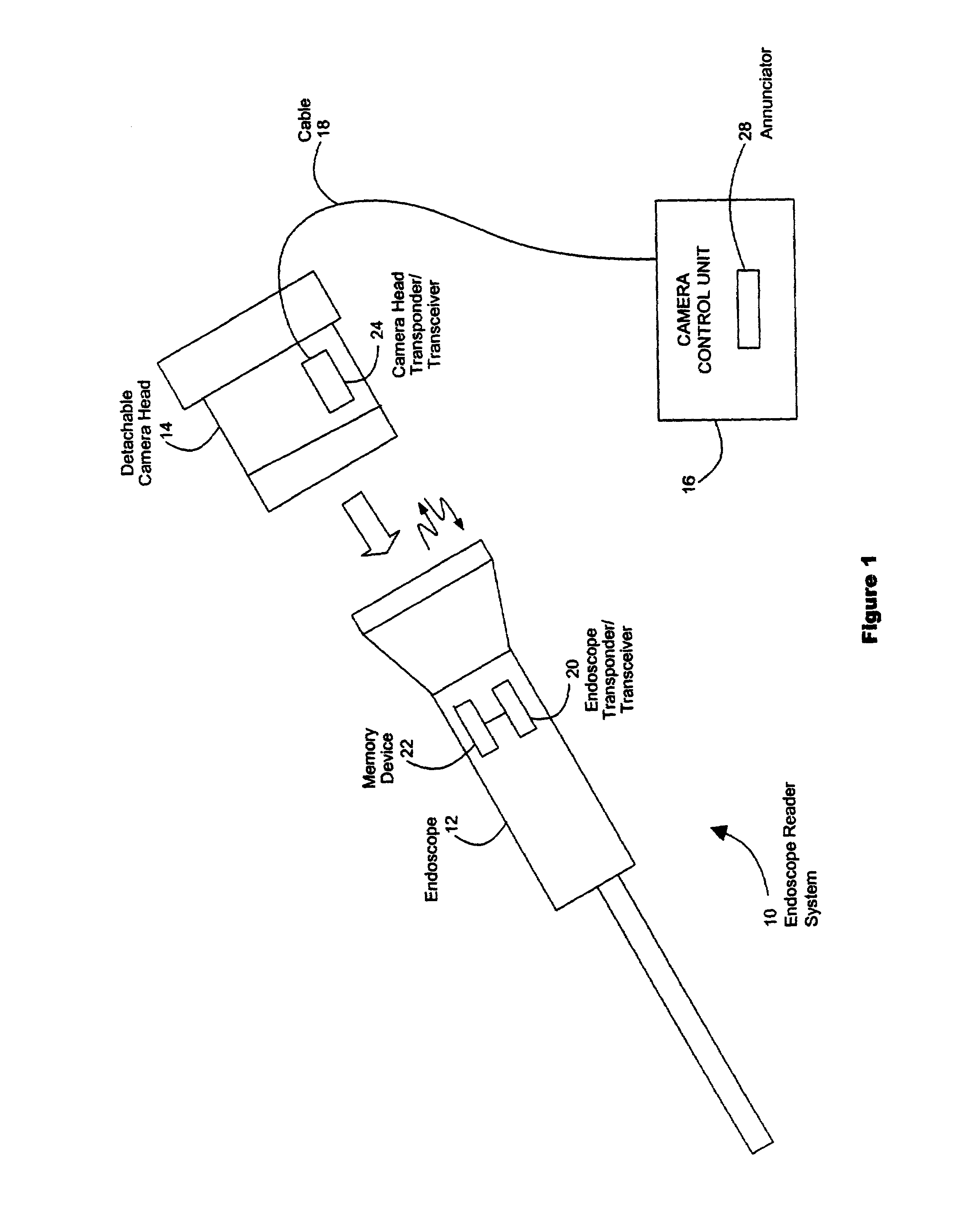
[0029]Referring to FIG. 1, an endoscopic system 10 for storing and transmitting electronic representations of endoscope characteristics is shown. In accordance with one advantageous embodiment, an endoscope transponder / transceiver 20 is mounted on an endoscope 12 and communicates with a camera head transponder / transceiver 24 mounted on a detachable camera head 14. Endoscope transponder / transceiver 20 and camera head transponder / transceiver 24 may be any type of short-range transponder / transceiver devices well known to those of ordinary skill in the art. Endoscope transponder / transceiver 20 and camera head transponder / transceiver 24 are set so that each is capable of both sending and receiving radio frequency signals to and from the other.

[0030]Endoscope transponder / transceiver 20 is coupled to a memory device 22. Memory device 22 is capable of storing and providing electronic representations of parameters of endoscope 12 to endoscope transponder / transceiver 20. Memory device 22 may ...


PUM


Abstract

A system for automatically setting video signal processing parameters for an endoscopic video camera system based upon characteristics of an attached endoscope, with reduced EMI and improved inventory tracking, maintenance and quality assurance, and reducing the necessity for adjustment and alignment of the endoscope and camera to achieve the data transfer.

Description

FIELD OF THE INVENTION[0001]This invention relates to endoscopic video camera systems, where the video camera electronically identifies an attached endoscope and automatically sets system parameters in accordance with certain endoscope parameters. Additionally, the endoscope is electronically identified for manipulating, (i.e., reading information from, updating and then writing information to the endoscope) for the purposes of endoscope use and maintenance, inventory tracking and control, and monitoring of various other endoscope parameters.BACKGROUND OF THE INVENTION[0002]An endoscope is an elongated, tubular structured medical device that is inserted into body cavities to facilitate examination by medical professionals. The endoscope includes a telescope with an objective lens at its distal end. The telescope includes an image-forwarding system, which in rigid endoscopes is typically a series of spaced-apart lenses. In flexible endoscopes, typically, the image-forwarding system i...

Claims


Application Information

Patent Timeline
Patent Type & Authority Patents(United States)
IPC IPC(8): H04N7/18A61B1/00A61B1/04G02B23/24H04N5/225H04N5/232
CPCA61B1/00059A61B1/042G02B23/2484H04N5/23203H04N5/23209A61B1/00016A61B1/0002A61B1/00029A61B1/00055H04N2005/2255A61B2560/0276A61B1/00062H04N23/555H04N23/66H04N23/663
Inventor AMLING, MARC R.CHATENEVER, DAVID
Owner KARL STORZ IMAGING INC
Why Eureka
Try Eureka