Flicker detection apparatus, a flicker correction apparatus, an image-pickup apparatus, a flicker detection program and a flicker correction program

a flicker correction and flicker detection technology, applied in the field of flicker correction apparatus, flicker detection apparatus, flicker detection program and flicker correction program, can solve the problems of difficult to determine the case when lateral stripes occur in images, difficult to detect flicker in cases, etc., to improve the quality of images picked up under flicker light sources, the effect of extracting flicker components

Active Publication Date: 2007-10-30
ADVANCED INTERCONNECT SYST LTD
View PDF30 Cites 25 Cited by
  • Summary
  • Abstract
  • Description
  • Claims
  • Application Information

AI Technical Summary

Benefits of technology

[0010]Hence, it is possible to emphasize the variation of flicker components compared with the variation of brightness of a subject itself, at the time of varying shutter time. Thus, it is possible to extract flicker components effectively from an image where the light and shade of a subject coexist. Therefore, the occurrence of flicker can be detected with high accuracy, even if a subject is picked up normally. Thus, the quality of an image picked up under a flicker light source can be improved.
[0058]Hence, it is possible to extract flicker components even if a normal subject is picked up without using a special subject having an entire pure white surface. Thus, the quality of an image picked up under a flicker light source can be improved thereby, even if the shutter timing of each line of an image pick up means is different.

Problems solved by technology

However, in an image-pickup apparatus using an exposure method similar to a focal plane shutter system, there is a problem that lateral stripes occur in an image depending on specific shutter time, when an image is picked up with a flicker light source.
On the other hand, in the case of picking up an image of normal scenery under a flicker light source, it is difficult to determine a case when lateral stripes occur due to the affect of flicker, or a case when such stripes occur due to a difference of high brightness on the scenery itself, if lateral stripes which appear are observed.
Hence, in the conventional method, it is difficult to detect the occurrence of flicker in a case when a subject such as scenery or a person is picked up normally.

Method used


Image

  • Flicker detection apparatus, a flicker correction apparatus, an image-pickup apparatus, a flicker detection program and a flicker correction program
  • Flicker detection apparatus, a flicker correction apparatus, an image-pickup apparatus, a flicker detection program and a flicker correction program
  • Flicker detection apparatus, a flicker correction apparatus, an image-pickup apparatus, a flicker detection program and a flicker correction program

Examples


Embodiment Construction

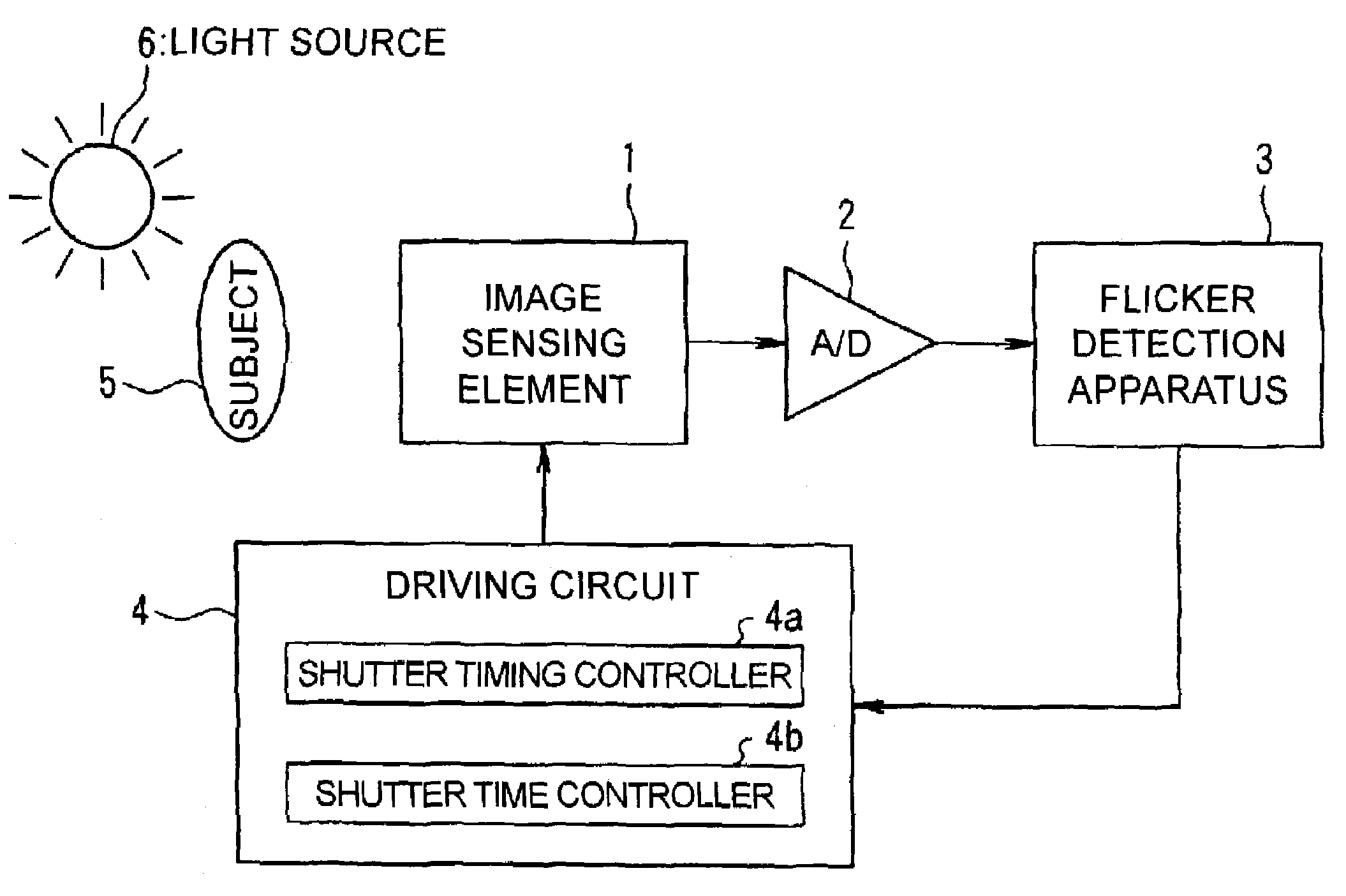
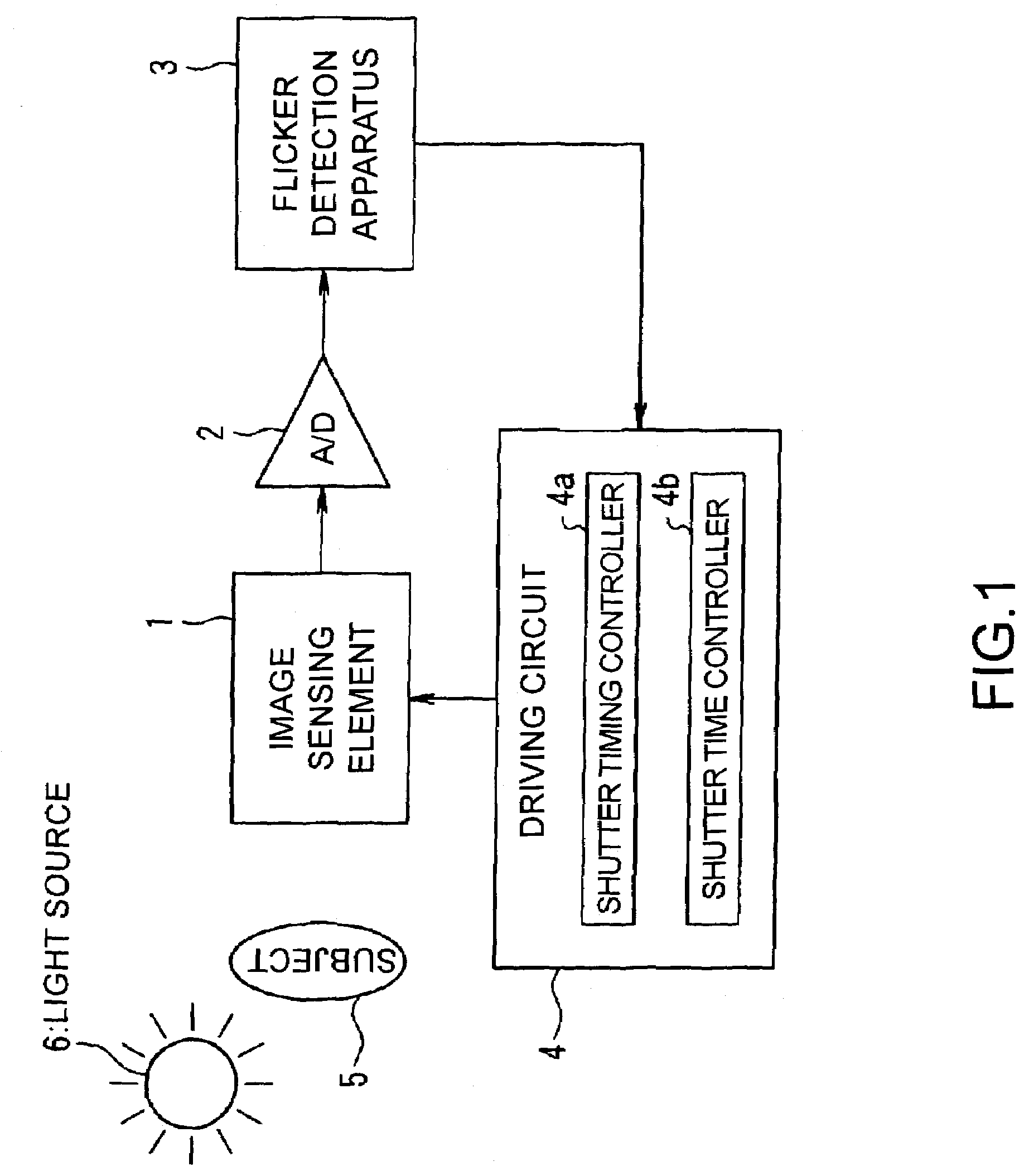
[0072]A method of flicker detection with regard to an embodiment of the present invention will be explained with reference to the accompanying drawings. FIG. 1 shows a schematic diagram of one embodiment of the present invention. In FIG. 1, an image-pickup apparatus comprises an image sensor element 1, an A / D converter 2 which converts an analog image signal output from the image sensor element 1 into a digital image signal, a flicker detection apparatus 3 for detecting flicker based on an image sensed by the image sensor element 1 and a driving circuit 4 to drive the image sensor element 1.

[0073]Further, the driving circuit 4 includes a shutter-timing controller 4a and a shutter-time controller 4b. The shutter-timing controller 4a controls shutter timing of the image sensor element 1 for each line. The shutter-time controller 4b controls the shutter time of the image sensor element 1 for each line. Here, the image sensor element 1 picks up an image by using a device like a CMOS sen...


PUM


Abstract

A flicker detection apparatus takes in a plurality of images having different shutter times from the image sensing element and judges whether flicker occurs or not based on a variation of flicker components extracted from these images so that the accuracy of flicker detection on picking up a normal image can be improved.

Description

BACKGROUND OF THE INVENTION[0001]1. Technical Field of the Invention[0002]The present invention is related to a flicker detection apparatus, a flicker correction apparatus, an image-pickup apparatus, a flicker detection program and a flicker correction program. In particular, it can be applied preferably to an image-pickup apparatus which implements exposure control via a focal plane shutter system.[0003]2. Background Technology and Problems to be Solved by the Invention[0004]In a conventional image-pickup apparatus, an image is picked up by shutter operation for each line by using a device like a CMOS sensor and using an exposure method similar to a focal plane shutter system.[0005]However, in an image-pickup apparatus using an exposure method similar to a focal plane shutter system, there is a problem that lateral stripes occur in an image depending on specific shutter time, when an image is picked up with a flicker light source. Namely, shutter timing is different for every line ...

Claims


Application Information

Patent Timeline
Patent Type & Authority Patents(United States)
IPC IPC(8): H04N9/73H04N5/21H04N5/235
CPCH04N5/235H04N23/70
Inventor ARAZAKI, SHINICHI
Owner ADVANCED INTERCONNECT SYST LTD
Why Eureka
Try Eureka