
Communication between software elements

a software element and communication technology, applied in the field of communication between software elements, can solve the problems of single present-day server being overwhelmed by both the computational load and the network traffic, and the approach will become very quickly impractical, and achieve the effect of reducing the workload of the present-day server

Inactive Publication Date: 2007-10-30
BRITISH TELECOMM PLC
View PDF11 Cites 94 Cited by
  • Summary
  • Abstract
  • Description
  • Claims
  • Application Information

AI Technical Summary

Benefits of technology

[0028]Holding the entire communication state in the communication software element associated with any given software element allows the application software element and communication software element assembly to communicate and move in particularly dynamic fashion. The messaging consequently enabled, carried out on a per element basis, allows for continuity of communication between software elements even if they move in such a dynamic way.
[0036]Again, holding the entire communication state in the communication software element associated with any given software element allows the application software element and communication software element assembly to communicate and move in particularly dynamic fashion. The messaging consequently enabled, carried out on a per element basis, allows for continuity of communication between software elements even if they move in such a dynamic way.

Problems solved by technology

It will be clear that such an approach will very quickly become impractical as the number of clients rises.
However, as soon as the number of clients begins to rise this approach also becomes impractical.
If, for example, hundreds of clients were to interact in any non-trivial manner, a single present-day server would simply be overwhelmed by both the computational load and the network traffic.
Further, as the game environment evolves, it may well be the case that the computational tasks required to maintain it change.
The developer of applications such as large multi-player games therefore faces a considerable challenge in working with such a highly dynamic and distributed architecture.
It will be clear that, in particular, the problem is posed of allowing such real-time, low latency communication between the distributed game components as will allow a highly dynamic and distributed multi-player game to be played.
However, many problems would immediately arise including:(a) Each client would have to continually create and destroy connections to all the relevant server processes (where the definition of ‘relevant’ changes regularly) introducing problems of latency and processing overhead.(b) Game components changing their location (i.e. moving between processes) would create problems of location tracking and data sequencing.
However, whilst the enforced sequencing problem is removed, so is, for example, any concept of data sequencing or reliable delivery.
Whilst these are powerful techniques, they are not applicable to highly time-critical and traffic volume sensitive applications.
Thus, these present-day approaches are simply not able to provide a solution to the problem outlined above.

Method used


Image

  • Communication between software elements
  • Communication between software elements
  • Communication between software elements

Examples


Embodiment Construction

Server Cluster Architecture

[0046]FIG. 3 illustrates one example of a simple server cluster (300) and network configuration suitable for use with this exemplary embodiment of the invention. The suitable server computer cluster (300) is shown as having a first server computer (301), a second server computer (302) and a third server computer (303) interconnected via a Local Area Network (LAN) (304).

[0047]Suitable computers will be well known, running for example varieties of Unix (Irix, Linux and Solaris) or Microsoft Windows™.

[0048]As will be discussed further below with reference to FIG. 7, a number of client computers (not shown in FIG. 3) may be connected to the server computer cluster 300.

[0049]The first server computers (301) hosts first and second server processes (305, 306), and the second server computer (302) hosts a third server process (307). Each such server process (305, 306, 307) hosts one or more application related components (308, 310312, 314). As discussed above, eac...


PUM


Abstract

It will be well known that a so-called object-oriented approach to computer programming has become widespread over the past few years and applications such as large multiplayer games are no exception. A number of approaches to allowing objects to communicate with one another have been developed. One set of these approaches relate to allowing so-called distributed objects, which is to say objects distributed over a client / server system, to communicate with one another. With reference to applications such as large multiplayer games, dynamic real time distributed communications between mobile objects must be considered. Present day techniques, involving the use of simple TCP / IP or UDP / IP, CORBA or DCOM are unable to provide such real time dynamic performance. According to one aspect of the invention a method of providing communication between two or more application software elements is provided comprising associating each application software element with a communication software element through which to send and / or receive messages, holding the communication state of the associated application software element in each communication software element, allowing each application software element to communicate with other application software elements by sending and receiving messages through the respectively associated communication software elements and allowing each application software element and associated communication software element to move. Holding the communication state in the communication software element associated with each application software element allows the application software element and communication software element assembly to communicate and move in particularly dynamic fashion. Messaging consequently enabled, carried out on a per software element basis, allows for continuity of communication between objects even if they move in a dynamic fashion.

Description

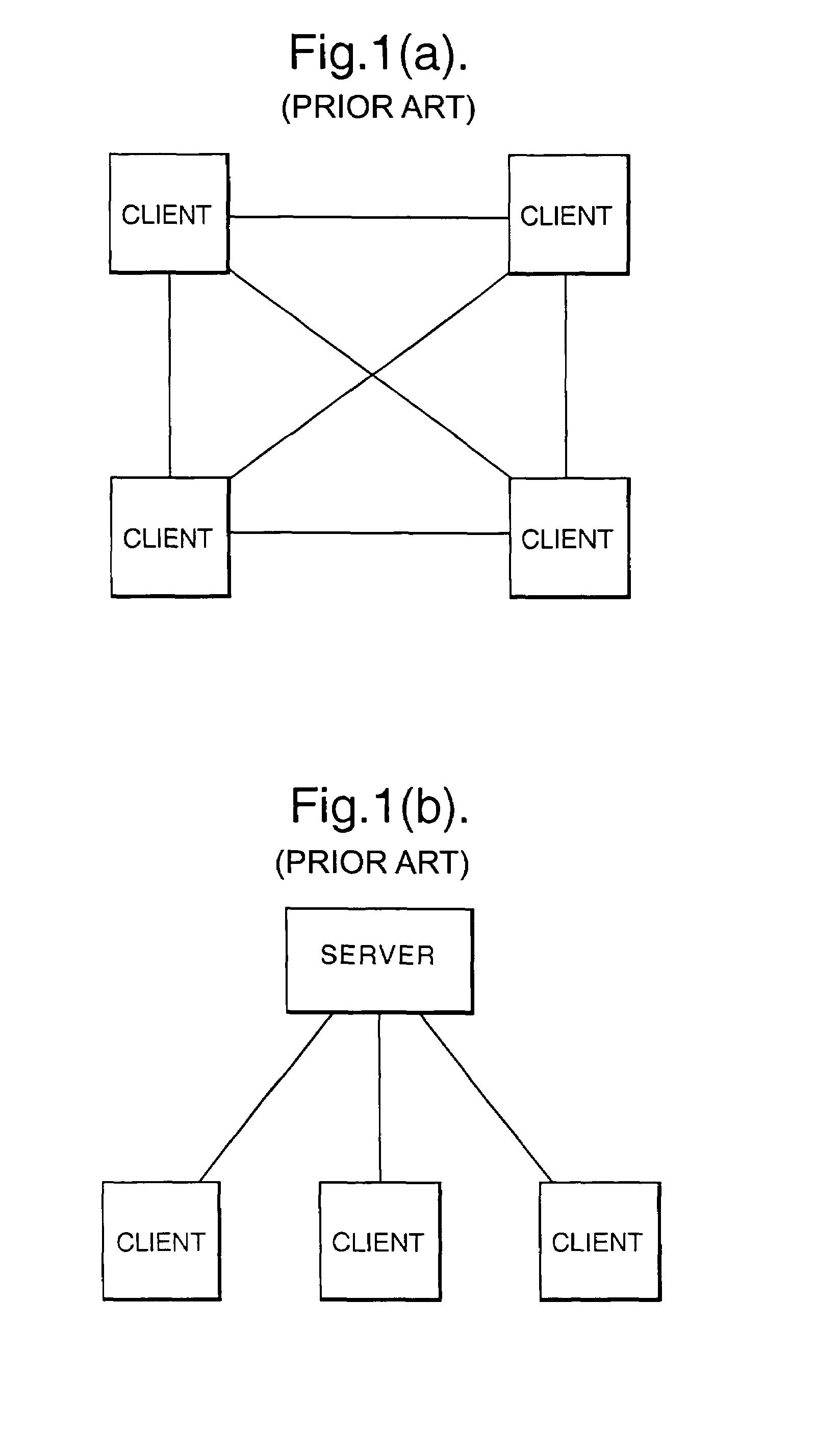
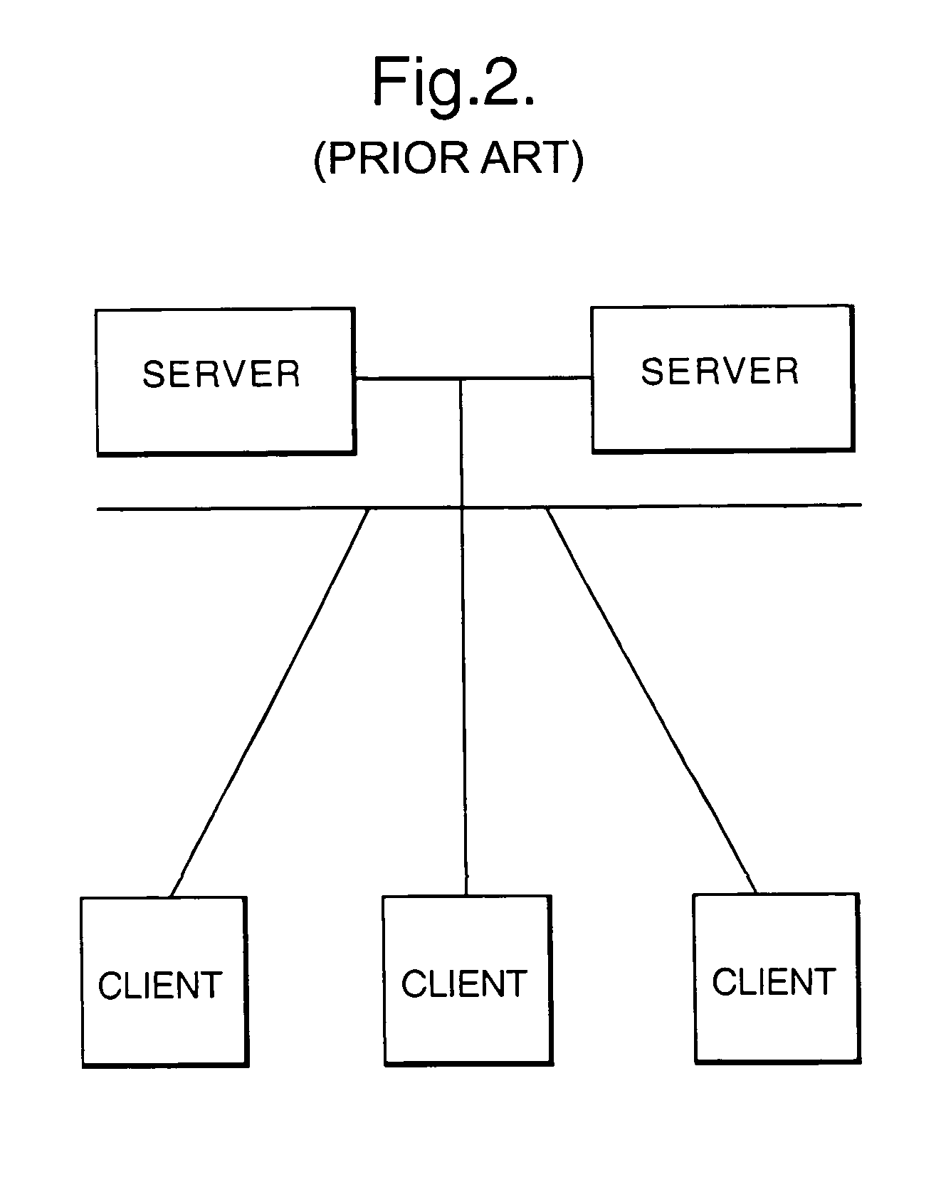
BACKGROUND[0001]1. Field of Art[0002]The present application relates to provided a method of and apparatus for providing communication between two or more software elements. The invention disclosed herein has particular, but not exclusive, application to dynamic real-time distributed systems with highly mobile software elements.[0003]2. Related Art[0004]Well known examples of present-day architectures used by such applications to enable the interaction of a number of clients will be discussed having regard to FIGS. 1(a)-(b) and 2.[0005]FIG. 1(a) illustrates a very simple interconnection of each client to all other clients. It will be clear that such an approach will very quickly become impractical as the number of clients rises. It might easily be wished that, for example, one hundred clients are to interact.[0006]FIG. 1(b) illustrates a more sophisticated approach where each client is connected to a single central server. The concept of a client / server arrangement and associated te...

Claims


Application Information

Patent Timeline
Patent Type & Authority Patents(United States)
IPC IPC(8): G06F3/00G06F13/00G06F9/44G06F9/46A63F13/12G06F15/16
CPCG06F9/465
Inventor POWERS, SIMON JHINDS, MICHAEL R
Owner BRITISH TELECOMM PLC
Learn More