
Intelligent client architecture computer system and method

a client architecture and computer system technology, applied in the field of distributed processing computer systems, can solve the problems of complexities in managing the intelligent client architecture application, and achieve the effects of quick and easy authored and developed, friendly user interface, and fast and easy operation

Active Publication Date: 2005-10-20
LANDMARK TECH PARTNERS
View PDF20 Cites 55 Cited by
  • Summary
  • Abstract
  • Description
  • Claims
  • Application Information

AI Technical Summary

Benefits of technology

[0009] The present invention relates to systems and methods for distributed application management and soft object referencing in distributed processing systems. The present invention provides a simple, powerful, and elegant manner in which to distribute computer resources in a networked environment using distributed application management. Distributed application management is a manner of distributing tasks between computers in a network that augments client and server technologies with core services necessary to partition data management tasks. Unlike the client-server and n-Tier architectures where tasks are dispatched to a computer based on the technical type of task (e.g., database, presentation, application logic, etc.), in the distributed application management environment of the present invention, tasks are distributed based upon the boundaries of a particular business transaction. For example, if an application must execute a series of business rules, data reads, writes, updates, and presentation rendering tasks to complete the business transaction, such as applying a check to an open accounts payable, then all of these tasks are dispatched to the computer supporting that user. That is, the PC or client device operated by the user receives all the software to execute the transaction. This distributed application management frees the central server computers from having to manage the different aspects of this business transaction until it is completed and reported back to the central servers as completed. Of course, a business transaction may be any communicative action or activity involving two parties or things that reciprocally affect or influence each other and is not limited to a commercial exchange, transfer of goods, services, or funds.
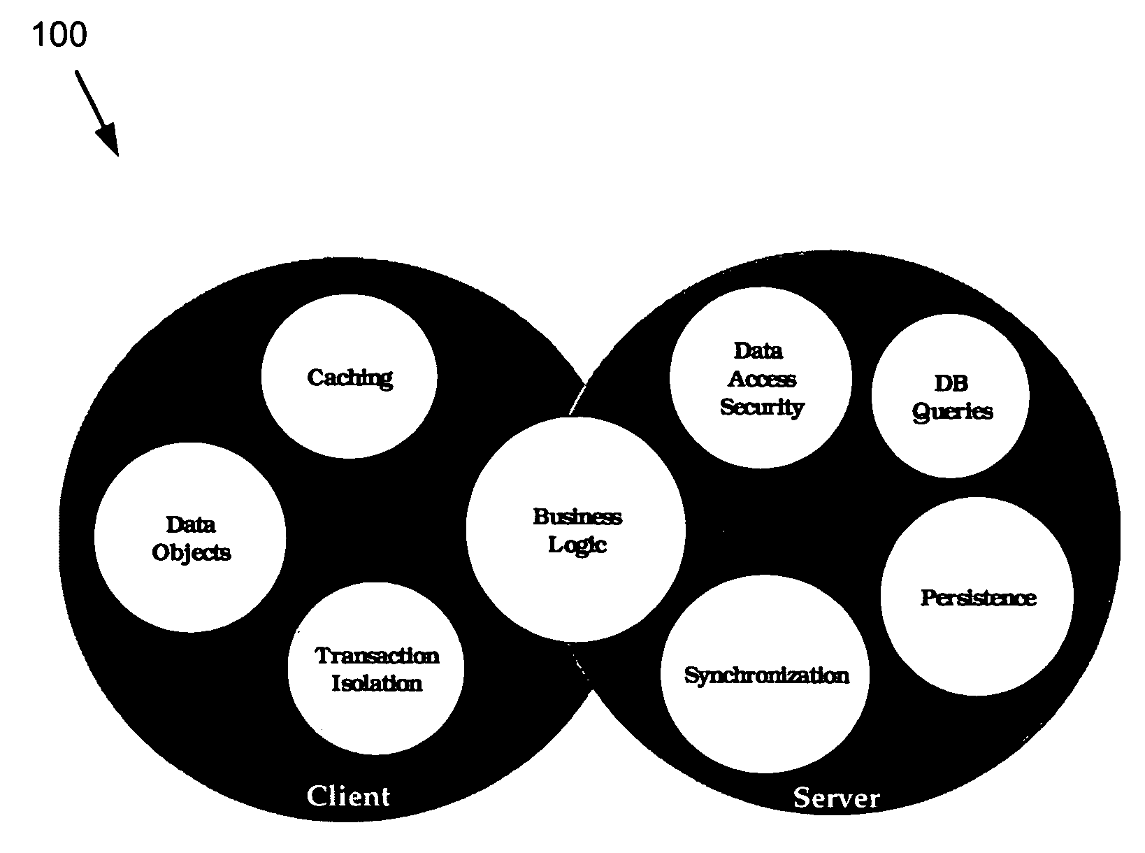
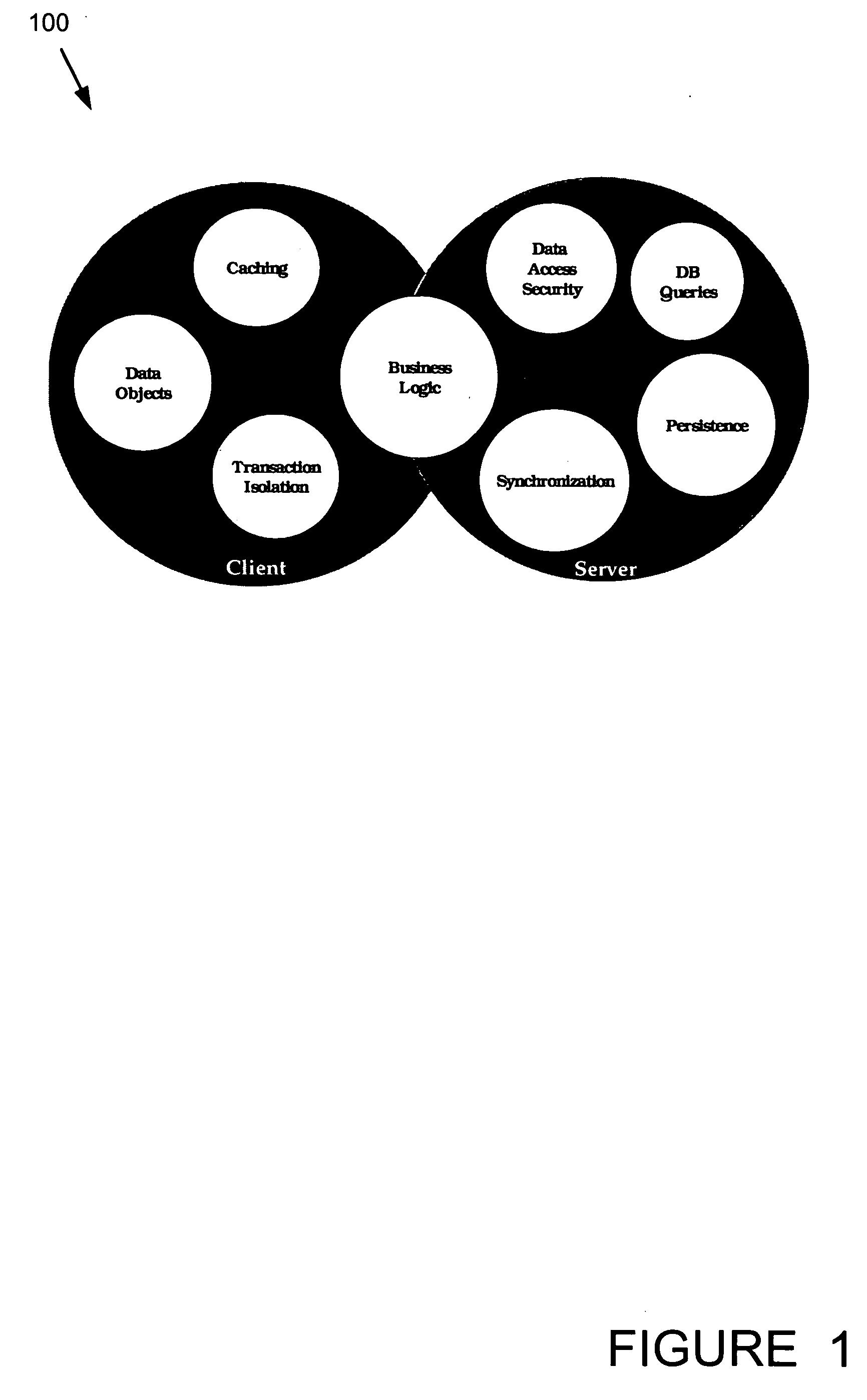
[0010] The distributed application management of the present invention can temporarily distribute the entire application necessary to complete the business transaction to the client device. This distribution scheme and architecture allows the system to use the client-side computing power to manipulate the application and data in ways that would be resource-prohibitive if a shared server resource were used to accomplish these tasks. Transaction management, caching, and manipulation of business objects may be performed independently on the client, while persistence, synchronization, and query execution may take place on the server. Tasks that should be performed on the client are performed on the client, and tasks that should be performed on the server are performed on the server. This delineation provides a tremendous improvement in the performance and flexibility of Internet and other networked applications.
[0011] For example, the present invention may employ client-side computer power to perform language translation, voice recognition, integrated telephony, or rules-based data analysis. Additionally, the native processing power of a dedicated client device may be used to present a “rich client” that supports rapid and intuitive end user interaction with the application.

Problems solved by technology

There are a number of complexities in managing this intelligent client architecture application once it is distributed.

Method used


Image

  • Intelligent client architecture computer system and method
  • Intelligent client architecture computer system and method
  • Intelligent client architecture computer system and method

Examples


Embodiment Construction

[0030] The invention is described in detail with particular reference to certain preferred embodiments, but within the spirit and scope of the invention, it is not limited to such embodiments. It will be apparent to those of skill in the art that various features, variations, and modifications can be included or excluded, within the limits defined by the claims and the requirements of a particular use.

[0031] The following exemplary embodiment describes the data distribution and management process of the present invention in the context of a client-server business application use case. However, it should be understood that the present invention may also be used in embedded computing, grid computing, and other data and application architectures.

[0032] The present invention extends the functionality of current client-server architectures as well as those thin-client and n-Tier distributed computer applications by distributing data objects to the proper network nodes to support local ...


PUM


Abstract

A collision detection and data synchronization mechanism operates to expand the speed and capability of distributed applications. The execution environment employs collision detection and data synchronization to distribute data objects to appropriate network nodes to support local processing. The collision detection and data synchronization mechanism defines the set of processes and algorithms used to track distributed data objects and to manage changes to the distributed objects throughout a network of intelligent computing devices. Data and code are distributed to local computing devices necessitating tracking and synchronizing updates. The system and method ensures that data updates received during the course of a local transaction do not unwillingly affect the results of other transactions by notifying the local computing devices of changes to the data that are subject of the transaction. These conflicts are then resolved in the applications, and notification of the resolution is sent to the remaining intelligent computing devices.

Description

FIELD OF THE INVENTION [0001] The invention relates generally to distributed processing computer systems. More particularly, the invention relates to systems and methods for distributed application management and soft object referencing in distributed processing systems to allocate data objects to network nodes to support local processing. BACKGROUND OF THE INVENTION [0002] In the past, there have been three major application architectures that have been used to build and deploy software that supports end-user processes. This is in contrast to lower level software that supports hardware and software processes such as operating systems. These three architectures have closely mirrored the evolution of the hardware environment. First, in the beginning of the computer age, hardware was centralized, expensive and very tightly controlled. This was typified by the mainframe computer with optional dedicated terminals to support end users. A monolithic or host-based application architecture ...

Claims


Application Information

Patent Timeline
IPC IPC(8): G06FG06F12/00G06F17/30
CPCG06F9/466G06F17/30575G06F17/30008G06F16/273Y10S707/99952G06F16/2322G06F16/27
Inventor TSINMAN, IGORMAZUR, JAMIEMCGUIRE, ROBERT E.
Owner LANDMARK TECH PARTNERS
Learn More