Magnetic impact tool

a technology of magnetic impact and tool, which is applied in the direction of manufacturing tools, percussive tools, portable drilling machines, etc., can solve the problems of inability to carry out tightening and loosening work, inability to use, and inability to tighten and loosen work, so as to facilitate handling, simplify the configuration of the changing device, and reduce the total length of the tool.

Inactive Publication Date: 2005-07-19
MATSUSHITA ELECTRIC WORKS LTD
View PDF10 Cites 30 Cited by
  • Summary
  • Abstract
  • Description
  • Claims
  • Application Information

AI Technical Summary

Benefits of technology

[0018]The magnetic bypass device may be configured to take the form of a spiral spring that is elastically deformable in the axial direction of the magnetic hammer, wherein one end is positioned close to the end face of the magnetic hammer, and the other end is configured to be able to be pulled and moved by the changing device. Owing to the elasticity of the magnetic bypass device, the action of the magnetic bypass device is thereby synchronized with the changing device, and the changing device operates so as to be returned to its initial position, then the configuration of the changing device can be simplified.
[0019]The magnetic bypass device may also be configured to be able to be moved by the changing device toward or away from the magnetic hammer in a radial direction that is orthogonal to the axial center of the magnetic hammer. The total length of the tool can thereby be shortened, and the tool can be made easier to handle, then operability in narrow areas can be improved in comparison with a configuration whereby the magnetic bypass device moves in the axial direction of the magnetic hammer.
[0020]The changing device may also be adapted to act by way of the centrifugal force of the rotation produced by the motor. The changing device can thereby automatically change the distribution ratio of the magnetic flux produced by the magnetic bypass device in accordance with the rotational speed of the motor, increase the magnetic impact torque during times of high rotational speed, decrease the magnetic impact torque during times of low rotational speed, and optimally maintain work efficiency irrespective of whether the required torque is high or low.
[0021]The changing device may be configured such that the magnetic bypass device moves in coordination with the trigger for setting the output of the motor. The trigger for setting the output of the motor can thereby be operated in accordance with the intention of the operator, and the magnetic impact torque can be freely controlled.
[0022]The plate serving as the magnetic bypass device may take a substantially conical shape that protrudes toward the magnetic hammer. The opposing surface areas of the magnetic hammer and the magnetic bypass device are thereby increased, and the distribution ratio of the magnetic flux from the magnetic hammer to the magnetic bypass device and magnetic anvil can be varied considerably. As a result, the range of magnetic impact torques can be expanded from very low to very high, a tool that is capable of handling very thin to very thick screws can be obtained, and there is no need for the operator to carry several types of power tools.
[0023]The changing device may be adapted to allow the movement distance and movement timing of the magnetic bypass device to be set in accordance with the force with which the tool is pressed to the object to be fastened. The magnetic impact torque is thereby increased when the pressing force is high, the magnetic impact torque is reduced when the pressing force is low, and the user interface between the operator and the tool is improved.

Problems solved by technology

However, (1) the inertial force of motor assembly 3 cannot be used when the screw is locked and is further tightened from a condition in which the stalling torque of the motor assembly 3 has been exceeded, or when the locked screw is loosened, so magnetic impact action does not occur and tightening and loosening work cannot be carried out.
(2) In the case of a thin screw, the load torque from the screw never exceeds the magnetic attraction torque, so the operator constantly receives a big reaction force to the arm, and the arm is tired.
In addition to these drawbacks, a large reaction force is applied to the arm when the screw becomes seated.

Method used


Image

  • Magnetic impact tool
  • Magnetic impact tool
  • Magnetic impact tool

Examples


first embodiment

[0042](First Embodiment)

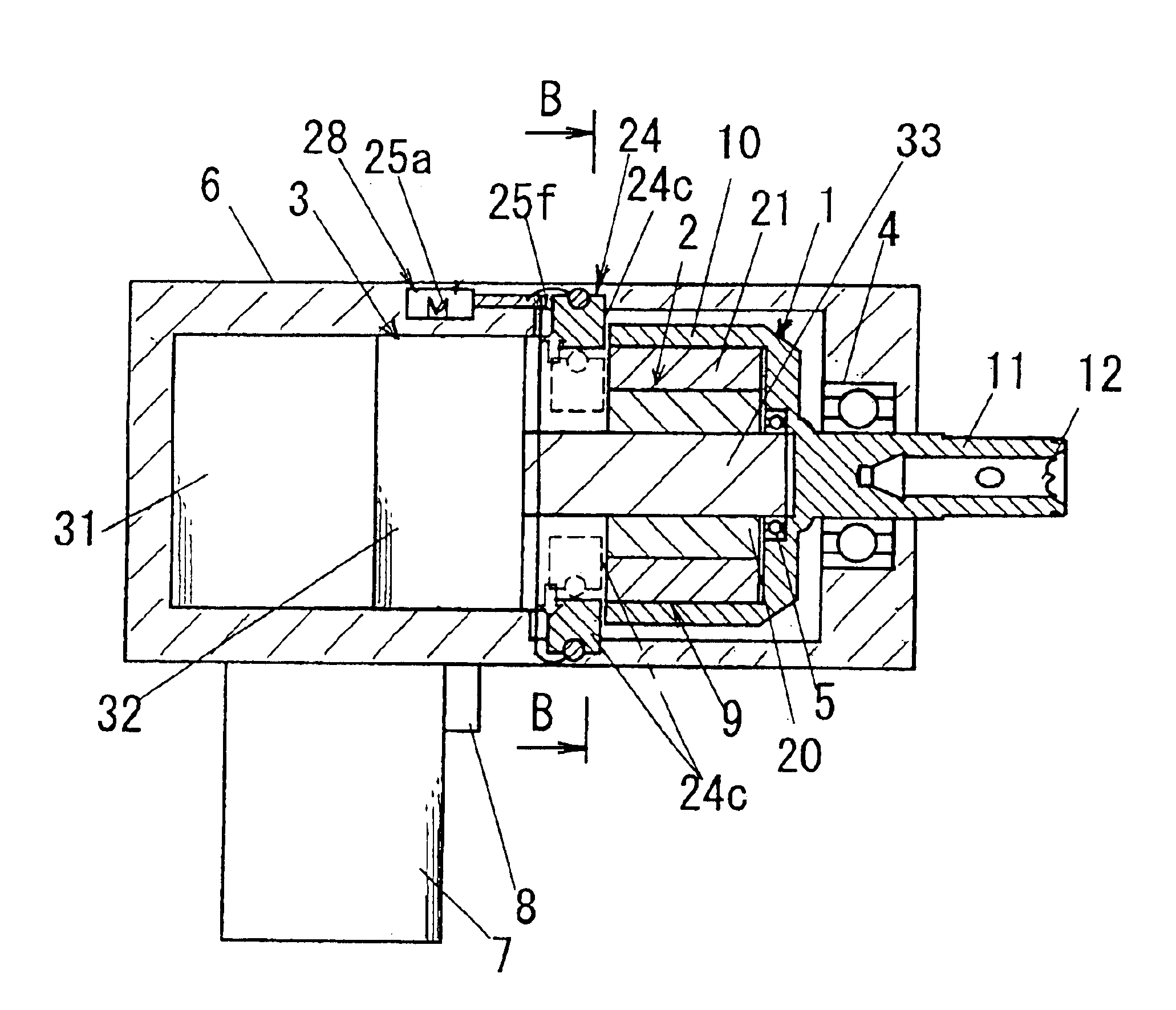
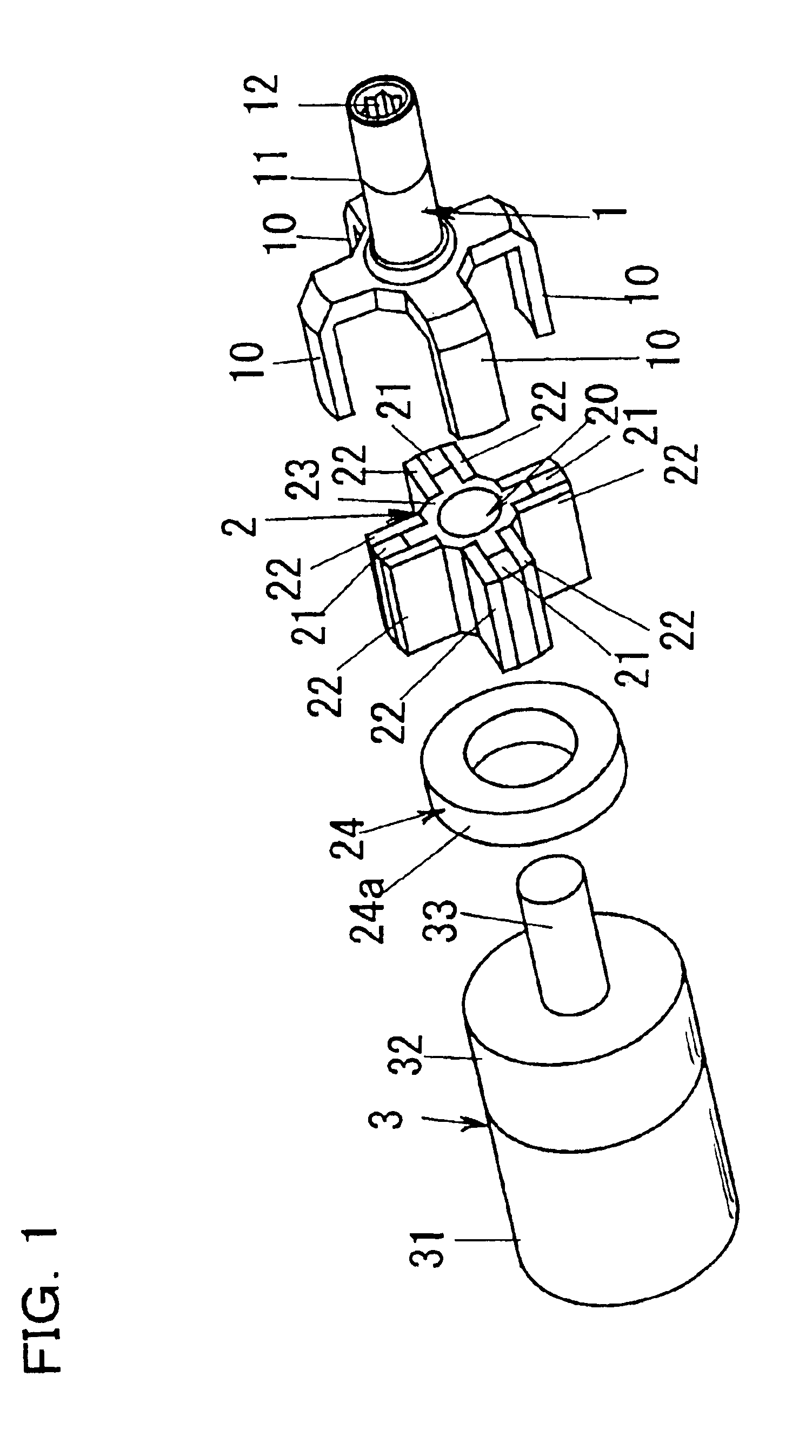
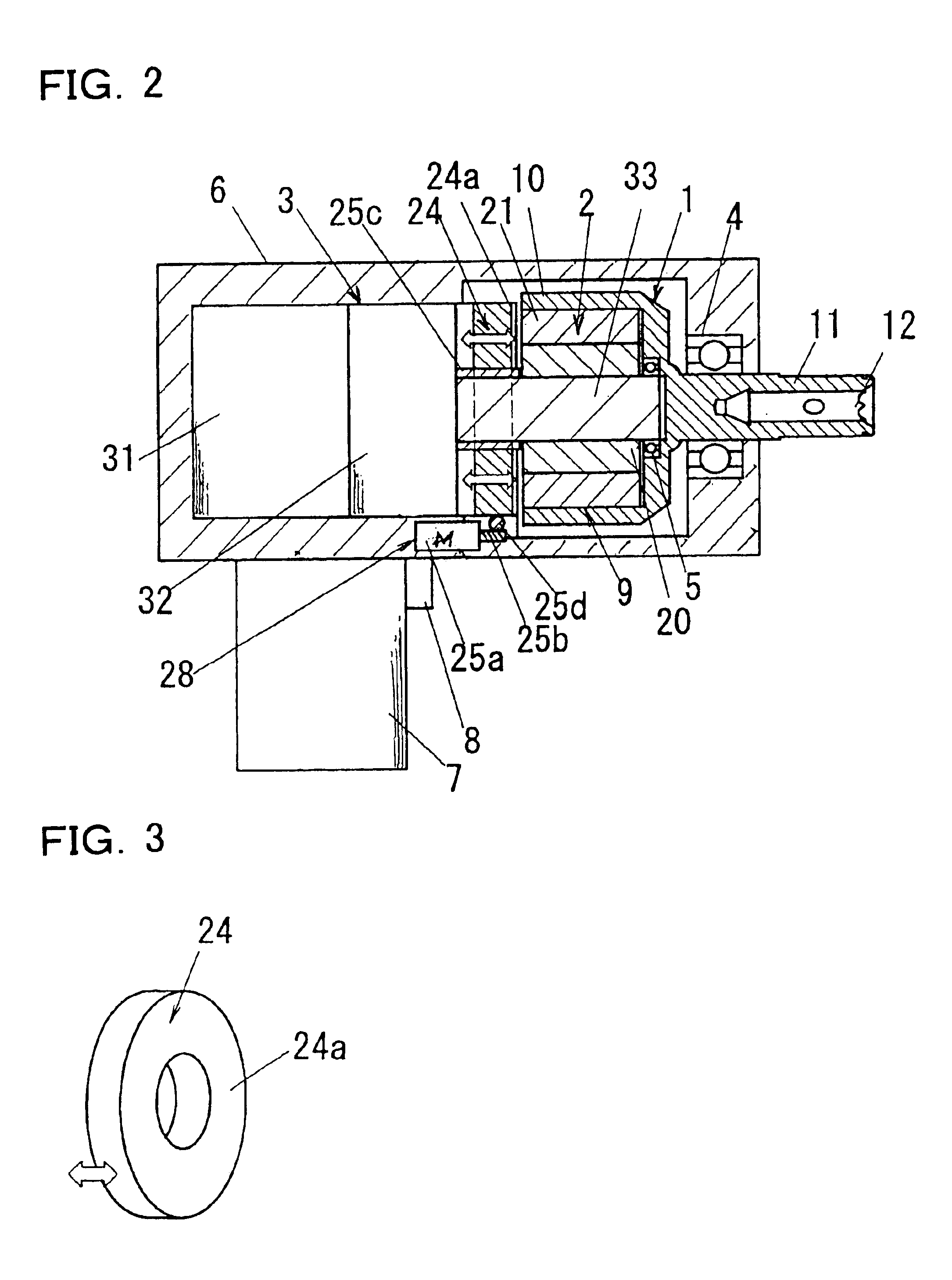
[0043]FIGS. 1 to 3 show a magnetic impact tool (hereinafter referred to as tool) according to the first embodiment of the present invention. The basic structure of this tool is the same as the structure for generating impact torque in a non-contact manner shown in the above-described FIGS. 15 to 17; the same symbols are assigned to common portions and their description is omitted (the same applies hereinafter); and characteristic structures are assigned new symbols and described. This tool comprises a magnetic bypass device 24 for distributing magnetic flux between the magnetic anvil 1 and the magnetic hammer 2, and a changing device 28 for changing the distribution of magnetic flux by the magnetic bypass device 24. In this tool, the distribution ratio of the magnetic flux that flows from the magnetic hammer 2 to the magnetic anvil 1 and the magnetic bypass device 24 can be varied by means of the changing device 28. The torque generated between the magnetic h...

second embodiment

[0050](Second Embodiment)

[0051]FIGS. 4 and 5 show a magnetic impact tool according to the second embodiment. In this embodiment, an annular plate 24a composed of a magnetic material as a magnetic bypass device 24 is provided with an enlarged hole diameter, and is mounted with a tolerance on the drive axle 33. The plate 24a has a shaft 27 that is orthogonal to the axial center of the magnetic hammer 2 in a position outside of or on the external periphery of a magnetic hammer 2, and this shaft 27 is rotatably supported by bearings 61 disposed in the case 6. The changing device 28 has a return spring 26 and a solenoid or other direct-acting actuator 25e for causing the plate 24a to tilt. The magnetic flux distribution from the magnetic hammer 2 to the magnetic anvil 1 can be changed and the torque generated on the magnetic anvil 1 varied by tilting the plate 24a with the changing device 28. Here, the plate 24a is tilted by the tensile force of the actuator 25e, and when the drive of th...

third embodiment

[0053](Third Embodiment)

[0054]FIGS. 6 and 7 show a magnetic impact tool according to the third embodiment. In this embodiment, the magnetic bypass device 24 is configured with a spiral spring 24b composed of magnetic material. The internal end portion of the spiral spring 24b has an initial position in the vicinity of the end face of the magnetic hammer 2, and the external end portion of the spiral spring 24b is fixed to the case 6. The changing device 28 is configured with a direct-acting actuator 25e that is linked to the end of the internal end portion of the spiral spring 24b. When the internal end portion of the spiral spring 24b is pulled by the actuator 25e in a direction parallel to the drive shaft 33, the spiral spring 24b can be elastically deformed, then, the distribution of the magnetic flux between the magnetic hammer 2 and magnetic anvil 1 is changed. Consequently, the torque generated on the magnetic anvil 1 can be varied. By reversing the actuator 25e and eliminating...


PUM

PropertyMeasurementUnit
rotational impact forceaaaaaaaaaa
rotational forceaaaaaaaaaa
magnetic fluxaaaaaaaaaa

Abstract

There is provided a magnetic impact tool comprising a magnetic hammer driven by a motor, a magnetic anvil disposed so as to face the magnetic hammer, an output shaft that rotates together with the magnetic anvil, a magnetic bypass device for distributing magnetic flux between the magnetic anvil and the magnetic hammer, and a changing device for changing the distribution of magnetic flux with the magnetic bypass device, wherein a rotational impact force is magnetically generated in a non-contact manner for the magnetic anvil in conjunction with the rotation of the magnetic hammer. The torque generated between the magnetic hammer and magnetic anvil can be changed by varying the distribution ratio of the magnetic flux from the magnetic hammer to the magnetic anvil and magnetic bypass device by the changing device. Impact action can be generated, and screw tightening and loosening work can be carried out even if a low-torque motor is used. Magnetic impact action can be carried out and the load applied to operator's arm can be lightened even when working with a low-load screw wherein the load torque does not exceed.

Description

BACKGROUND OF THE INVENTION[0001]1. Field of the Invention[0002]The present invention relates to a magnetic impact tool for generating impact force through magnetism, and more specifically relates to a technique whereby a large magnetic impact action can be generated using a low-torque motor, and magnetic impact action can be performed even on a low-load screw in which the load torque does not exceed magnetic attraction torque.[0003]2. Description of the Related Art[0004]Conventional impact tools are used in operations in which machine screws are tightened with a bit such as a driver bit, and these tools comprises a hammer that is rotated with rotational force transmitted from a motor, an output shaft that meshes with the hammer and rotates, and a spring for urging the axially movable hammer toward the output shaft, wherein the output shaft is intermittently struck in the direction of hammer rotation and is rotated by means of a meshing portion between the hammer and output shaft. A...

Claims


Application Information

Patent Timeline
Patent Type & Authority Patents(United States)
IPC IPC(8): B25B21/02H02K7/10H02K49/00H02K7/14H02K49/10B25D13/00
CPCB25B21/02H02K7/10H02K7/145H02K49/10B25B21/026
Inventor SHINAGAWA, SOUNAKAYAMA, SATOSHISEKINO, FUMIAKI
Owner MATSUSHITA ELECTRIC WORKS LTD
Why Eureka
Try Eureka