Bow sight with controlled light intensity sight pin

a light intensity and control technology, applied in the field of bow sight with controlled light intensity sight pin, can solve the problems of low light visibility of the pin, the failure of the bow, and the complex modern bow, so as to reduce the inability to transmit light at the sighting end

Active Publication Date: 2007-11-06
BLACK GOLD ARCHERY LLC
View PDF22 Cites 32 Cited by
  • Summary
  • Abstract
  • Description
  • Claims
  • Application Information

AI Technical Summary

Problems solved by technology

Attachment of sight devices to a traditional bow such as a long bow or recurve bow posed problems with potential damage to the structural integrity of the bow sometimes causing the bow to fail particularly in laminated bows commonly referred to as fiberglass bows.
The modern bow is complex and can be considered a complex machine.
A major drawback of such sights was the visibility of the pins in low light and when viewed on certain backgrounds or targets.
Also, on overcast days, light can be sufficiently low to make the pins difficult to see and to see against a dark background as is not uncommon during hunting and also target shooting.
However, this required batteries which could “burn out” or the light bulb could “burn out”.
While effective, there were still disadvantages.
However, even these sights had drawbacks.
One major drawback of fiber optic sights is that when the sight is tuned for low light, to provide enough light absorption and projection in a low light condition, the light projection was often too intense during high light conditions.

Method used


Image

  • Bow sight with controlled light intensity sight pin
  • Bow sight with controlled light intensity sight pin
  • Bow sight with controlled light intensity sight pin

Examples


Embodiment Construction

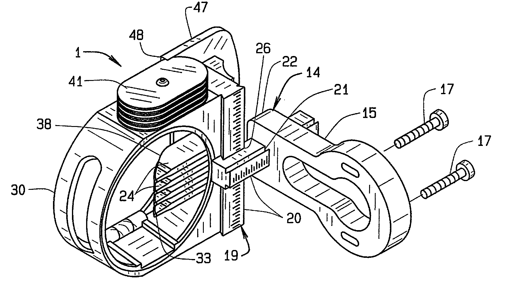
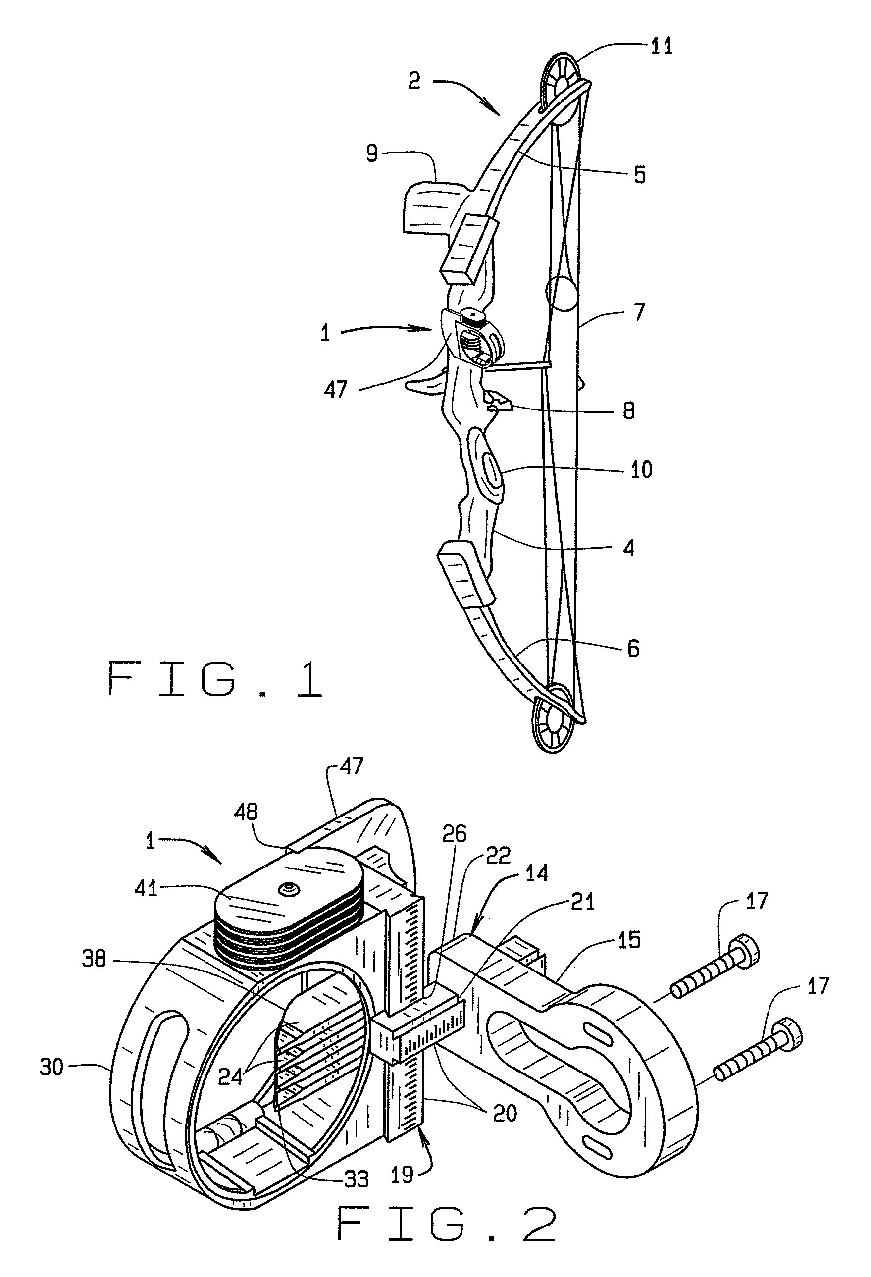
[0016]The referenced numeral 1 designates generally a sighting device for use on a bow designated generally 2. Although the sight device is shown as a bow sight, it is to be understood that the sight device can also be utilized with such long-range weapons as rifles, pistols and shotguns as well as other devices that are aimed visually.

[0017]The bow 2 can be of any suitable type known in the art and, as shown, includes a riser 4, a top limb 5, a bottom limb 6, a string 7, an arrow rest 8 and a hand grip 10. In the case of a compound bow, a cam 11 may be mounted at either or both of the ends of the limbs 5 and 6. Other known devices may be mounted to the bow including a stabilizer, a reel and a quiver 9. Typically bow risers 4 are made of a metal alloy and the limbs can be made of a flexible fiberglass or other fibrous material such as graphite fibers. The riser 4 typically is provided with means for mounting various devices to the bow and typically include threaded holes for receipt...


PUM


Abstract

An improved sighting device is provided. The sight may be used on a bow or other device which is typically sighted on an object during use. The sight includes at least one light-gathering fiber-optic fiber having at least one end from which absorbed light may be transmitted for viewing by a user. The fiber-optic fiber includes an associated element that regulates the amount of light absorbed in inverse proportion to the impinging light intensity in an automatic manner providing a more constant light intensity output.

Description

BACKGROUND OF THE INVENTION[0001]Sights for bows have evolved dramatically in the last few decades. An early sight provided a track mounted to the bow and allowed for both windage and elevation adjustment of pins movably mounted to the track. Usually a plurality of pins were used and set for different predetermined ranges for the individual bow and archer. These sights provided an advance in the art for archers over earlier sighting methods. One earlier method of aiming included the use of a consistent nock end anchor point and then using the arrow tip as the front sight which was an effective method for skilled archers but not necessarily for occasional archers. Bows have likewise advanced dramatically in the last few decades from the traditional long bow or recurve bow to the so called compound bow. Crossbows have also made similar advances. Attachment of sight devices to a traditional bow such as a long bow or recurve bow posed problems with potential damage to the structural int...

Claims


Application Information

Patent Timeline
Patent Type & Authority Patents(United States)
IPC IPC(8): F41G1/467F41G1/00
CPCF41G1/467
Inventor ELLIG, MICHAEL J.
Owner BLACK GOLD ARCHERY LLC
Why Eureka
Try Eureka