Apparatus for supporting a preform having a supporting core

a technology of apparatus and preform, which is applied in the field of apparatus for supporting preforms, can solve the problems of reducing the cooling stage considerably, affecting the uniformity and optical qualities of the preform in the re-heating zone, and reducing the time necessary, so as to reduce the risk of end-piece breaking or deformation of the preform, reduce the time necessary, and eliminate the human risk factor

Inactive Publication Date: 2007-11-06
DRAKA COMTEQ BV
View PDF17 Cites 5 Cited by
  • Summary
  • Abstract
  • Description
  • Claims
  • Application Information

AI Technical Summary

Benefits of technology

[0028]A first advantage of the present invention is that the mass of the preform is no longer a limiting factor. In particular, this makes it possible to increase the diameter or the length of preforms without any risk of an end-piece breaking or of the preform being deformed significantly under its own weight.
[0029]Another advantage of the present invention is that it is possible to make the preform-cutting stage automatic, thereby considerably reducing the time necessary for removing and storing a manufactured or built-up preform, eliminating the human risk factor, and improving the quality of the resulting preforms.

Problems solved by technology

Such a method gives rise to a significant loss of time due to preform cooling.
Any shortening of the cooling stage considerably increases operator accident risks.
However, locally re-heating a cooled preform, during the cutting stage, can have considerable adverse effects on the uniformity and the optical qualities of the preform in the re-heated zone.
In particular, cracks may occur.
Furthermore, the size of a preform is currently limited in particular by its weight.
Such sagging runs the risk of breaking an end-piece.
Moreover, such sagging can have adverse effects on the uniformity of the preform.

Method used


Image

  • Apparatus for supporting a preform having a supporting core
  • Apparatus for supporting a preform having a supporting core
  • Apparatus for supporting a preform having a supporting core

Examples


Embodiment Construction

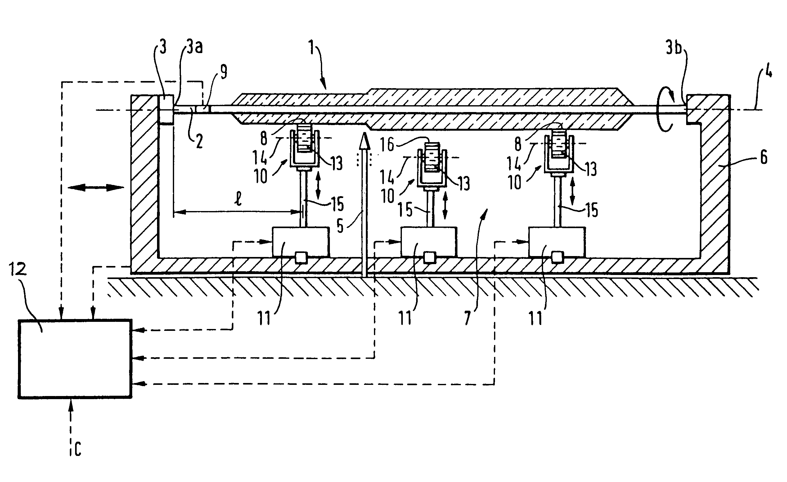
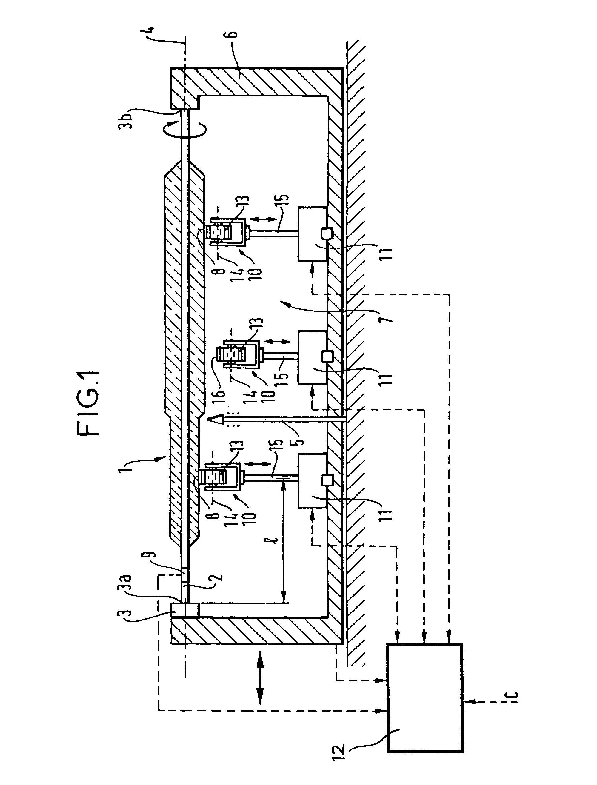
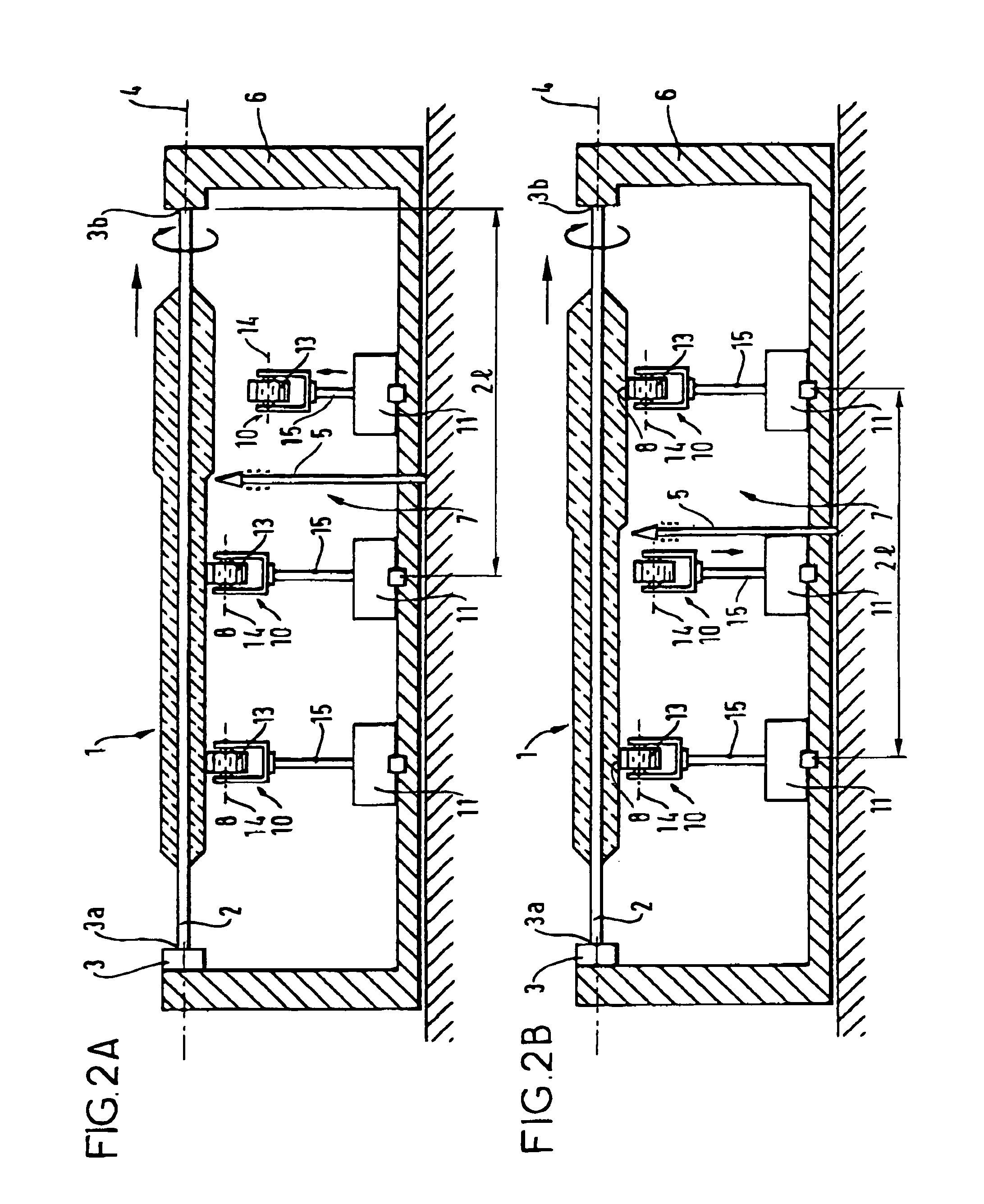
[0034]The apparatus of the invention is described in detail with reference to FIG. 1. As depicted in FIG. 1, the apparatus is designed to be mounted on a prior art installation for manufacturing or building up a preform 1 having a central supporting core 2. In known manner, the installation comprises at least rotation means 3 having a horizontal axis of rotation 4 and on which the supporting core 2 of the preform 1 to be manufactured or built up is mounted, and plasma-torch and material-supply means 5 disposed radially relative to said supporting core 2. In known manner, the installation makes it possible for the plasma-torch and material-supply means 5 to move in axial translation relative to and parallel to the supporting core 2 so as to make the preform 1 around the supporting core 2.

[0035]In the embodiment shown in the figures, the rotation means 3 are mounted on a moving frame 6 that moves in translation parallel to the axis of rotation 4, the plasma-torch and material supply m...


PUM

PropertyMeasurementUnit
diameteraaaaaaaaaa
diameteraaaaaaaaaa
diameteraaaaaaaaaa

Abstract

The invention relates to apparatus for supporting a preform manufactured in an installation for manufacturing or building up preforms having supporting cores, said installation including at least rotation means having a horizontal axis of rotation and two mounting points between which the supporting core of the preform to be manufactured or built up is mounted, plasma-torch and material-supply means disposed radially relative to said supporting core and being mounted to move in axial translation relative to and parallel to the supporting core so as to make said preform around said supporting core, said apparatus being wherein it includes controlled support means constituting additional localized abutment points between said mounting points for said preform being manufactured or built up.

Description

[0001]This is a continuation of application Ser. No. 08 / 555,178 filed Nov. 8, 1995, now U.S. Pat. No. 6,196,028, disclosure of which is incorporated herein by reference.[0002]The invention relates to apparatus for supporting a preform, an installation for manufacturing or building up an optical fiber preform and provided with such apparatus, methods implemented in such an installation, and preforms manufactured or built up using such methods.BACKGROUND OF THE INVENTION[0003]The invention relates more particularly to apparatus for supporting a preform manufactured or built up in an installation for manufacturing or building up preforms having central cores. This type of installation conventionally includes at least translation means and rotation means having a horizontal axis of rotation and on which the supporting core of the preform to be manufactured or built up is mounted, and plasma-torch and material-supply means disposed radially relative to said supporting core so as to make ...

Claims


Application Information

Patent Timeline
Patent Type & Authority Patents(United States)
IPC IPC(8): C03B29/02C03B33/085C03B37/014
CPCC03B37/01486C03B33/085Y02P40/57
Inventor HUMBERT, PATRICKRIPOCHE, PIERRELANDI, JOELGOUDEAU, JACQUES
Owner DRAKA COMTEQ BV
Why Eureka
Try Eureka