Friction stir welding apparatus

a friction stir and welding apparatus technology, applied in the direction of soldering apparatus, auxillary welding devices, manufacturing tools, etc., can solve the problems of complex whole structure of friction stir welding apparatus, inability to install, and inability to meet the needs of installation, so as to improve the welding quality of welded parts and enhance convenience

Inactive Publication Date: 2007-11-06
KAWASAKI HEAVY IND LTD
View PDF16 Cites 6 Cited by
  • Summary
  • Abstract
  • Description
  • Claims
  • Application Information

AI Technical Summary

Benefits of technology

[0011]When the base is fixed and the object to be welded is positioned on the base like this, the aforementioned arm which is necessary in the conventional art becomes unnecessary. By doing this, the apparatus can be miniaturized, and the structure thereof can be simplified, thus the manufacturing cost can be reduced. Further, the base does not move so that the installation space can be made smaller.
[0030]In the state that the object to be welded is clamped by the first and second clamping pieces like this, when the welding operation is performed, the welding operation can be performed in the state that the object to be welded is held. Further, when the object to be welded is supported by the backing member, the welding operation can be performed in the state that the object to be welded is prevented from deformation. By doing this, the object to be welded can be prevented from deformation and displacement during welding and the welding quality can be improved. Further, when the welding is finished, the clamping piece driving means is operated so as to separate the first clamping piece from the object, thus the first clamping piece is separated from the second clamping piece, and the object can be easily released from the holding state. The holding and release of the object can be easily switched like this and the welding operation can be performed in a short time.

Problems solved by technology

Therefore, a problem arises that the structure becomes inevitably large.
Further, in the friction stir welding apparatus 1, a moving space for the welding device 2 to move to the object 4 is required, so that a problem arises that a sufficiently large space for installation is necessary.
Further, the whole structure of the friction stir welding apparatus is complicated due to the arm 3, thereby, a problem arises that the maintenance and adjustment are difficult.
Further, according to the shape of the object 4, an operator should perform both the teaching operation and the exchange operation of a welding tool, thereby, a problem arises that the workability is lowered.

Method used


Image

  • Friction stir welding apparatus
  • Friction stir welding apparatus
  • Friction stir welding apparatus

Examples


Embodiment Construction

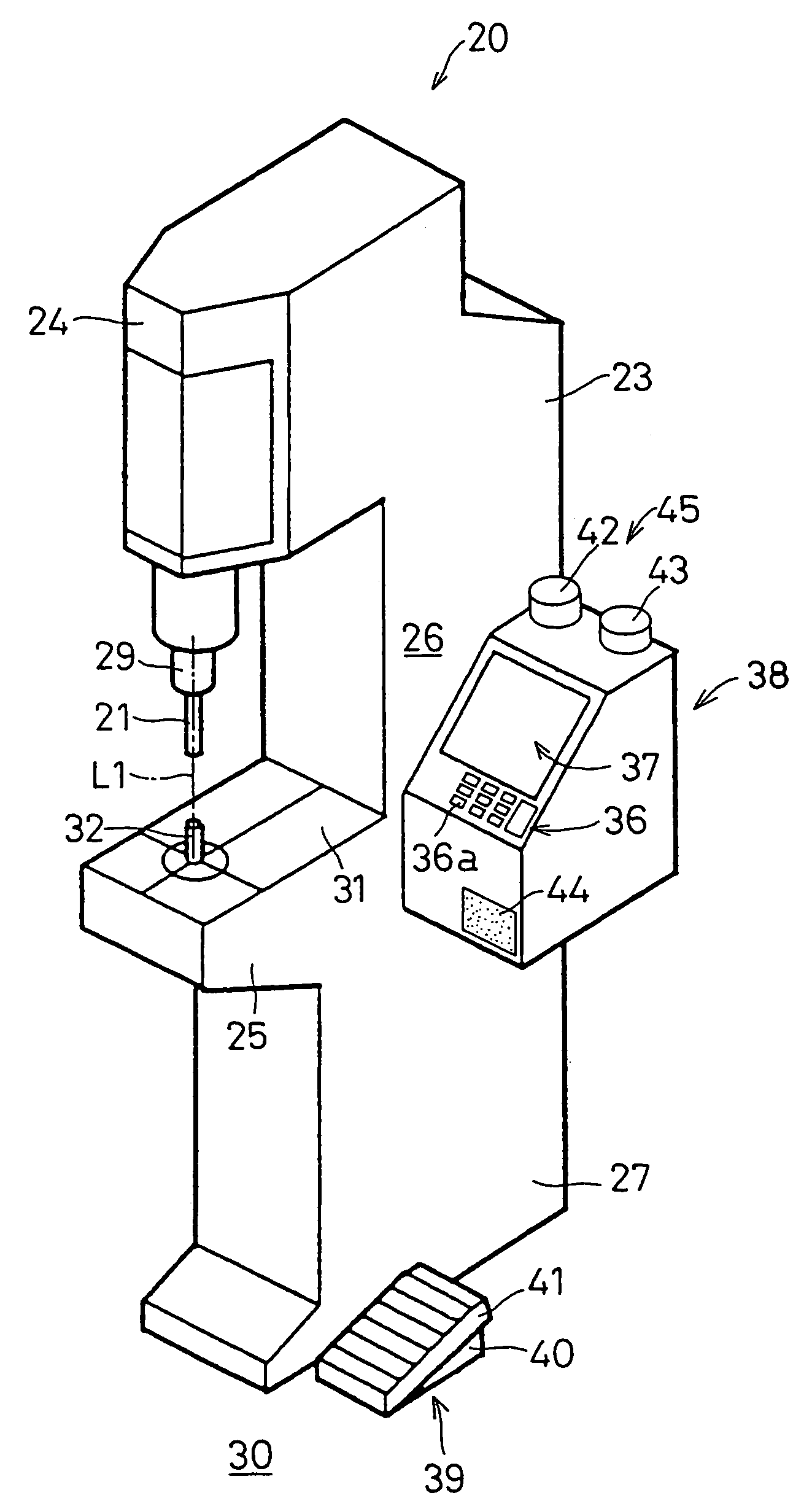
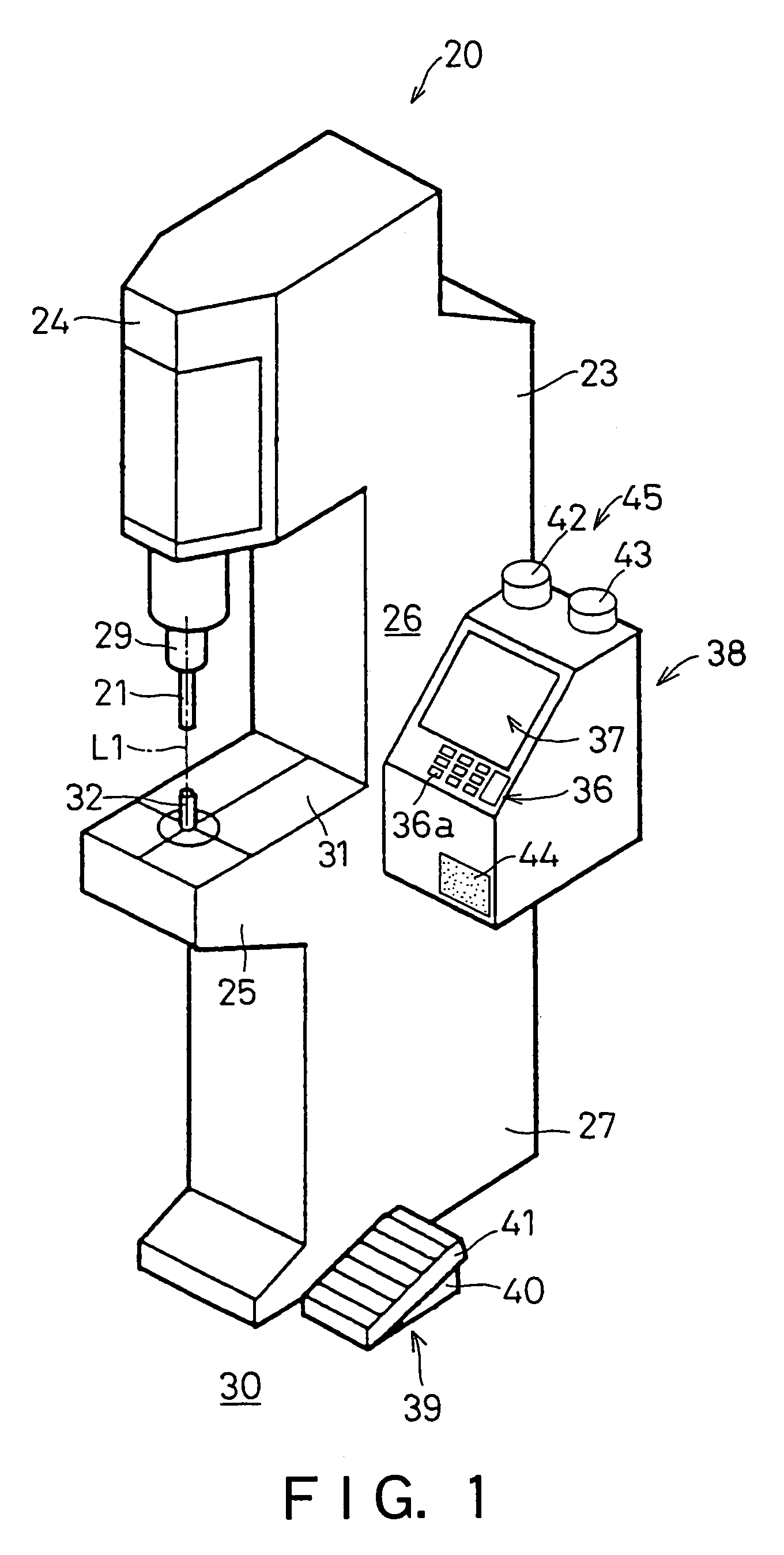
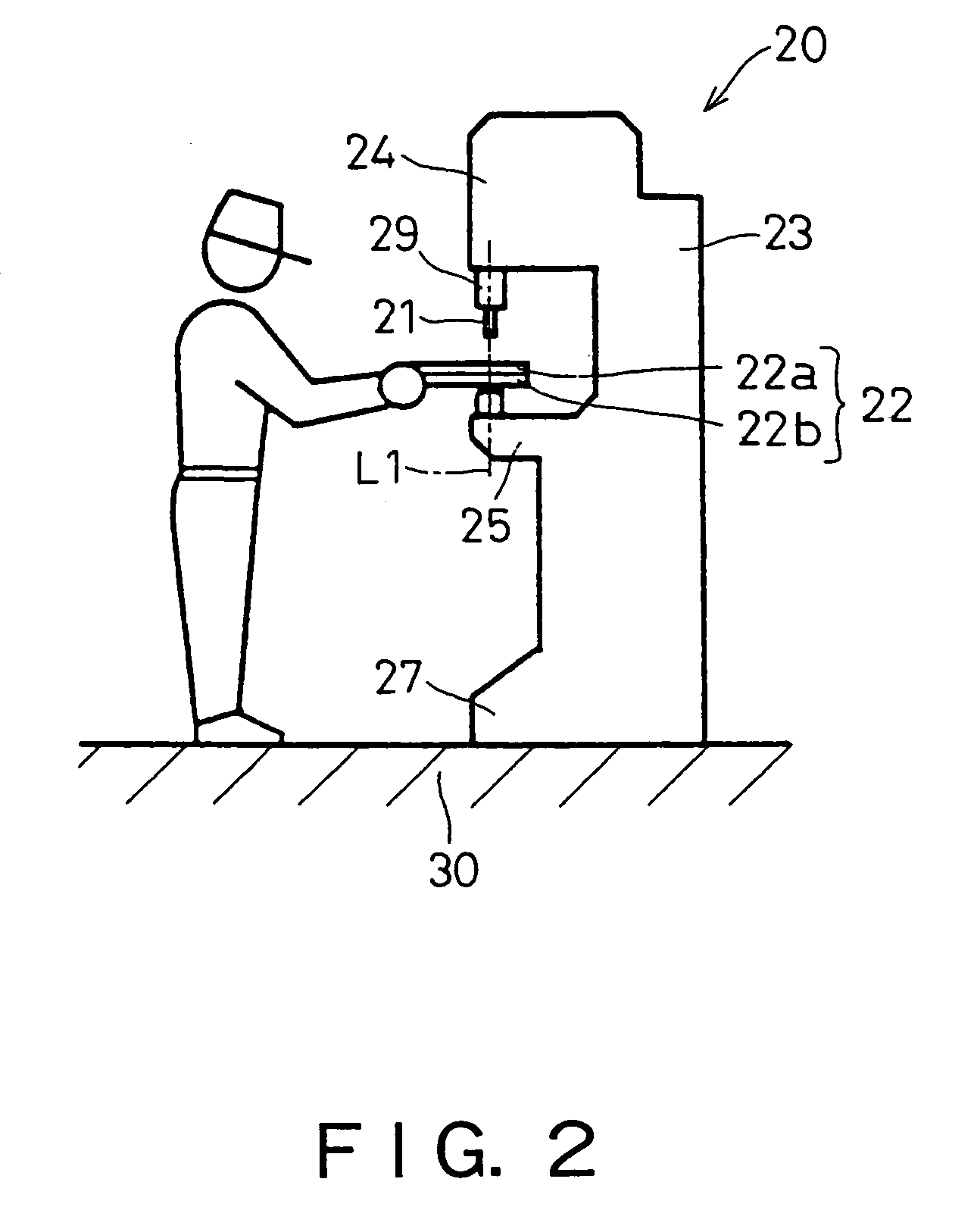
[0059]A friction stir welding apparatus 20 as an embodiment of the present invention which are shown in FIGS. 1 and 2, in the state that an object to be welded 22 is positioned on a base 23 by an operator, is an apparatus of frictionally stirring and welding the object 22, which is particularly used in spot welding. For example, the friction stir welding apparatus 20 is used to manufacture thin and medium-thin aluminum products and it is used to manufacture car bodies, boxes, design structures, and other stacked objects to be welded.

[0060]The friction stir welding apparatus 20 makes a columnar welding tool 21 rotate and come into contact with the object 22, presses the same against the object 22, and causes frictional heat between the welding tool 21 and the object 22. Next, the friction stir welding apparatus 20 makes the object 22 fluid by frictional heat and buries the welding tool 21 into the object 22. The welding tool 21 is buried up to the neighborhood of the respective bound...


PUM

PropertyMeasurementUnit
weightaaaaaaaaaa
spring forceaaaaaaaaaa
shapeaaaaaaaaaa

Abstract

The apparatus includes a base 23 fixed at a predetermine position, a tool holding jig 29, to which a welding tool 21 is mounted, installed on the base 23 rotatably about a preset reference axis L1 and movably along the reference axis L1, a tool rotation driving means for rotating the tool holding jig about the reference axis L1, and a tool movement driving means for moving the tool holding jig along the reference axis L1. The apparatus realizes miniaturization of the apparatus, simplification of the structure, and improvement of the operability.

Description

TECHNICAL FIELD[0001]The present invention relates to a friction stir welding apparatus for welding an object by a friction stir welding and more particularly to a friction stir welding apparatus suitably used for welding an object by a spot friction stir welding.BACKGROUND ART[0002]FIG. 25 is a drawing showing a friction stir welding apparatus 1 of the conventional art. The friction stir welding apparatus 1 includes a welding device 2 performing a welding operation and an arm 3 connected to the welding device 2 for positioning the welding device 2 for an object 4 to be welded. The welding device 2 is equipped with a tool holding jig 7 installed rotatably about a reference axis L1 and movably along the reference axis L1, a rotation motor for rotating the tool holding jig 7, and a displacement motor for moving the tool holding jig 7 along the reference axis L1. On the tool holding jig 7, a columnar welding tool 5 is mounted. The arm 3 may be made by a multi-joint robot and a tip 6 of...

Claims


Application Information

Patent Timeline
Patent Type & Authority Patents(United States)
IPC IPC(8): B23K31/02B23K20/12B23K37/04
CPCB23K20/123B23K20/1245B23K20/126B23K20/1265B25B5/06B23K37/0443B23K37/0408B23K2201/006B23K2201/185B23K2203/10B23K2101/006B23K2101/185B23K2103/10B23K20/12
Inventor KOGA, SHINJIINUZUKA, MASAYUKIFUJIMOTO, MITSUONISHIDA, HIDEHITOKANO, YUZO
Owner KAWASAKI HEAVY IND LTD
Why Eureka
Try Eureka