Reflective article and method of manufacturing same

a technology of reflective articles and printed articles, which is applied in the field of printed articles, can solve the problems of unpopular methods, unfavorable offset image methods, and difficult production of holographic images or holograms, and achieves the effects of reducing the cost of production, and improving the quality of printed articles

Inactive Publication Date: 2007-11-06
SERIGRAPH INC
View PDF48 Cites 28 Cited by
  • Summary
  • Abstract
  • Description
  • Claims
  • Application Information

AI Technical Summary

Benefits of technology

[0007]Therefore, it is an object of the present invention to provide a printing method and printed article which overcomes the drawbacks of the prior art. It is another object of the present invention to provide a printing method for printing reflective images on a printed article creating the illusion of depth, three-dimensionality, hidden images and motion on the printed article. It is yet another object of the invention to provide a printing method for printing images on a printed article which change, appear, disappear, and / or move as the viewing angle of the printed article is changed.

Problems solved by technology

However, these methods have not been commercially popular for various reasons.
The offset image method is undesirable in that special glasses are required to view the image.
Holographic images or holograms are difficult and expensive to produce.
However, embossing suffers from the drawback that an expensive press is necessary to perform the operation, and a die bearing the desired embossed pattern must be made for each application.
Further, the materials that can be used for embossing are limited because of the deforming nature of the embossing process.

Method used


Image

  • Reflective article and method of manufacturing same
  • Reflective article and method of manufacturing same
  • Reflective article and method of manufacturing same

Examples


first embodiment

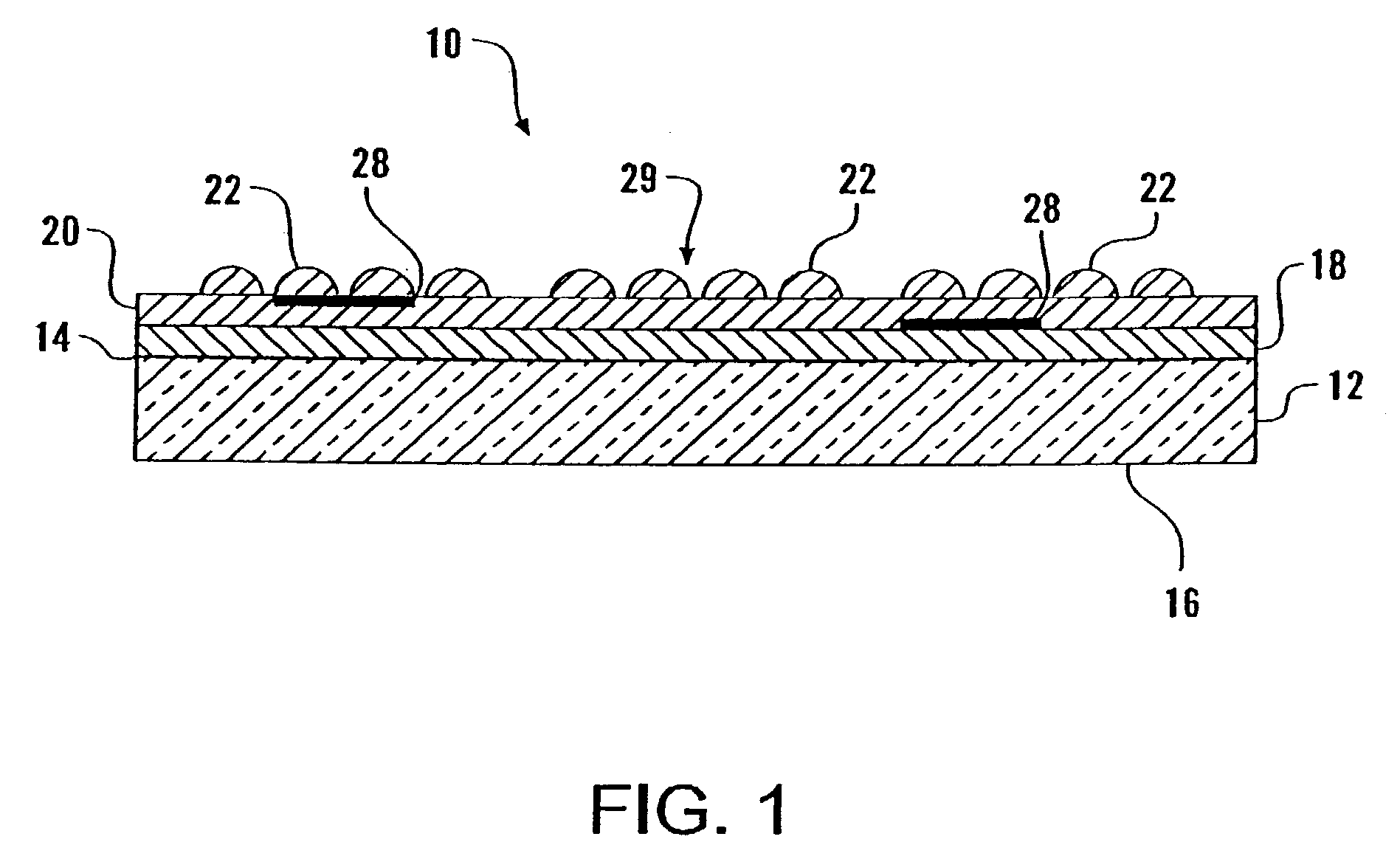
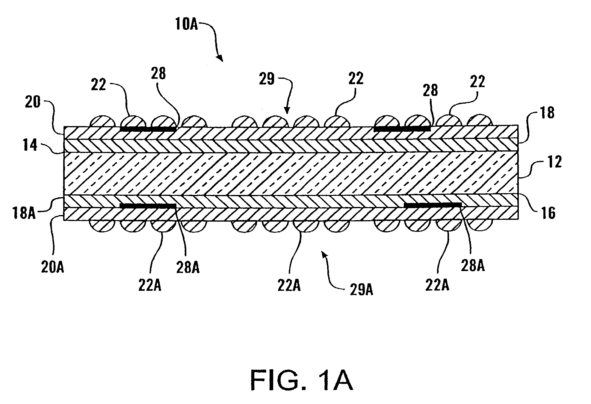
[0043]Referring now to the drawings, FIG. 1 illustrates a cross sectional view of a printed article produced in accordance with the present invention, depicted on a much enlarged basis over actual size. The printed article 10 includes a substrate 12 having a top surface 14 and a bottom surface 16. The substrate 12 can be formed of paper, cardboard, plastic, acrylic, glass, metal or any other suitable printable material.

[0044]A reflective ink layer 18 is printed over all or a portion of the top surface 14 of the substrate 12. The reflective layer 18 is preferably formed of reflective ink which is printed onto the substrate 12. The reflective layer 18 can be clear or have any color. The reflective layer 18 can be opaque, transparent, semi-transparent or translucent. The reflective layer 18 gives the printed article a shiny or glossy metallic appearance. Alternatively, the reflective layer 18 can be formed of a chrome film, diffraction film, metallic foil, holographic foil, roll leafin...

second embodiment

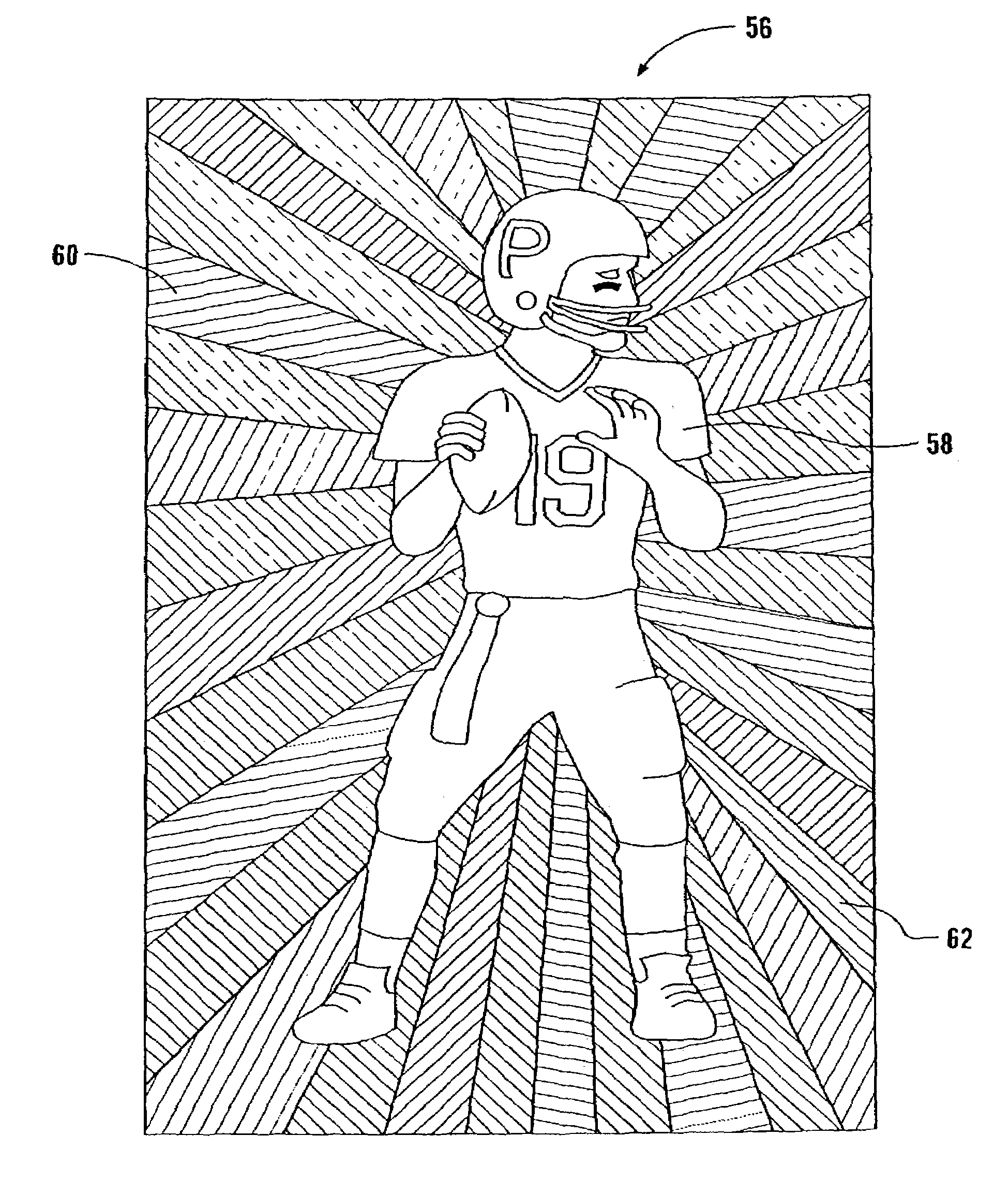
[0056]FIGS. 6, 6A, 7, 7A, 8 and 8A show variations or modifications 19, 19A, 21, 21A, 23 and 23A of FIGS. 5 and 5A. In FIGS. 6 and 6A, variations 19 and 19A include a graphic design or image 20, 20A printed on selected portions of the top 14 and bottom 16 surfaces of the substrate 12 with the textured pattern 29, 29A of lines 22, 22A printed on both the top 14 and bottom 16 surfaces of the substrate 12 and image 20, 20A. In FIGS. 7 and 7A, variations 21 and 21A include a graphic design or image 20, 20A printed on selected portions of the top 14 and bottom 16 surfaces of the substrate 12 with the textured pattern 29, 29A of lines 22, 22A printed only on the image 20, 20A. In FIGS. 8 and 8A, variations 23 and 23A include a graphic design or image 20, 20A printed on selected portions of the top 14 and bottom 16 surfaces of the substrate 12 and the textured pattern 29, 29A of lines 22, 22A printed only on the top 14 and bottom 16 surfaces of the substrate 12. The graphic design or image...

third embodiment

[0063]FIGS. 10, 10A, 11, 11A, 12 and 12A show variations or modifications 25, 25A, 26, 26A, 27 and 27A of the third embodiment, as shown in FIGS. 9 and 9A. In FIGS. 10 and 10A, variations 25 and 25A include a graphic design or image 36, 36A printed on selected portions of a reflective layer 34, 34A with a textured pattern 37, 37A of lines 40, 40A printed on a transparent glossy layer 38, 38A over both the reflective layer 34, 34A and image 36, 36A. In FIGS. 11 and 11A, variations 26 and 26A include a graphic design or image 36, 36A printed on selected portions of a reflective layer 34, 34A with a textured pattern 37, 37A of lines 40, 40A printed on a transparent glossy layer 38, 38A only over the image 36, 36A. In FIGS. 12 and 12A, variations 27 and 27A include a graphic design or image 36, 36A printed on selected portions of a reflective layer 34, 34A with a textured pattern 37, 37A of lines 40, 40A printed on a transparent glossy layer 38, 38A over only the reflective layer 34, 34...


PUM


Abstract

A reflective printed article includes a substrate having a top surface and a bottom surface with a graphic image printed thereon. A reflective or glossy ink layer is printed over the entire top surface of the substrate. A graphic image is printed over the reflective ink layer. The image may cover the entire portion of the reflective layer or only selected portions thereof. The graphic image includes hidden or latent images printed within the graphic image layers. An optional glossy layer of transparent ink may be printed over the graphic image. A textured pattern of lines is printed or applied in sections over the optional glossy layer or graphical image, with each line in the section printed at the same angle or orientation, with the lines of adjacent sections printed at different angles in order to reflect light in different directions to create the illusion of depth, three-dimensionality, hidden images and motion.

Description

CROSS-REFERENCE TO RELATED APPLICATION[0001]This application is a continuation-in-part of U.S. application Ser. No. 10 / 239,670, filed on Jan. 22, 2003 now abandoned, incorporated herein by reference.BACKGROUND OF THE INVENTION[0002]The present invention relates generally to a printed article, and more particularly to a reflective printed article having a graphic design such as a trading card, greeting card, sign, poster, label, decal, book cover, decorative panel, name plate, visual display and the like having a reflective image with a textured pattern printed thereon creating visual illusions of depth, three-dimensionality, hidden images and motion in the printed article.[0003]In order to attract the attention of consumers, many products are being manufactured with images that provide a unique and sensational visual presentation. To meet this demand, a variety of printing techniques have been developed to produce aesthetically pleasing visual effects, such as the appearance of dept...

Claims


Application Information

Patent Timeline
Patent Type & Authority Patents(United States)
IPC IPC(8): B24D15/00B41M3/00B41M3/14B42D15/00B44F1/10G02B27/22G09F19/12
CPCB41M3/148B42D15/02B44F1/10B44F7/00G02B27/2214G09F19/12B44F1/045B41M3/00B41M3/005B41M3/14Y10T428/1486Y10T428/24868G02B30/27
Inventor SCARBROUGH, JOEL SCOTTFAUL, DANIEL C.LASORSA, LOUIS
Owner SERIGRAPH INC
Why Eureka
Try Eureka