Ink jet printing method and ink jet printing apparatus

a printing head and ink jet technology, applied in printing and other directions, can solve the problems of affecting the image quality and affecting the operation of ink jet printers

Inactive Publication Date: 2007-11-06
CANON KK
View PDF4 Cites 6 Cited by
  • Summary
  • Abstract
  • Description
  • Claims
  • Application Information

AI Technical Summary

Benefits of technology

[0018]According to the above structure, the dot pattern formed based on preliminary ejection data is a pattern having a relation that the distance between any two dots other than the dot of highest-lightness is longer than the distance between a dot nearest to the dot of highest-lightness and the dot of highest-lightness, among a plurality of color dots. Therefore, the interval between low-lightness color dots can be set longer, and then the dot pattern preventing these dots from being perceived as a group of collected dots can be designed easily. More specifically, when the patterns are designed under a condition to arrange a plurality of color dots in an area of a predetermined length, the interval between low-lightness color dots can be set longer than that in a pattern in which respective dots are arranged equally spaced. The predetermined length in the above condition can be determined as a length obtained by deriving the quantity of preliminary ejection (the number of times of ejection) necessary for a single scanning for one color ink during the printing for instance on printing paper of A3 format, based on viscosity increasing property of ink, scanning speed of the printing head, and the like, and dividing the width of the scanning direction of the A3 format printing paper by this number of times of ejection.
[0019]The printing can be realized without deteriorating the printing quality by the paper preliminary ejection, because forming dots which are perceived as a group of collected dots is prevented by using a preliminary ejection pattern as mentioned above.

Problems solved by technology

More specifically, in the case of printing on a large sized printing medium, the throughput tends to lower because as much time is necessary for the printing head to scan.
In addition, when printing on a large sized printing medium, the ejection orifice in the printing head remains exposed for a long period of time.
However, the paper preliminary ejection sometimes degrades the image quality for usual ink jet printers in which the printing is performed using a plurality of ink colors.

Method used


Image

  • Ink jet printing method and ink jet printing apparatus
  • Ink jet printing method and ink jet printing apparatus
  • Ink jet printing method and ink jet printing apparatus

Examples


first embodiment

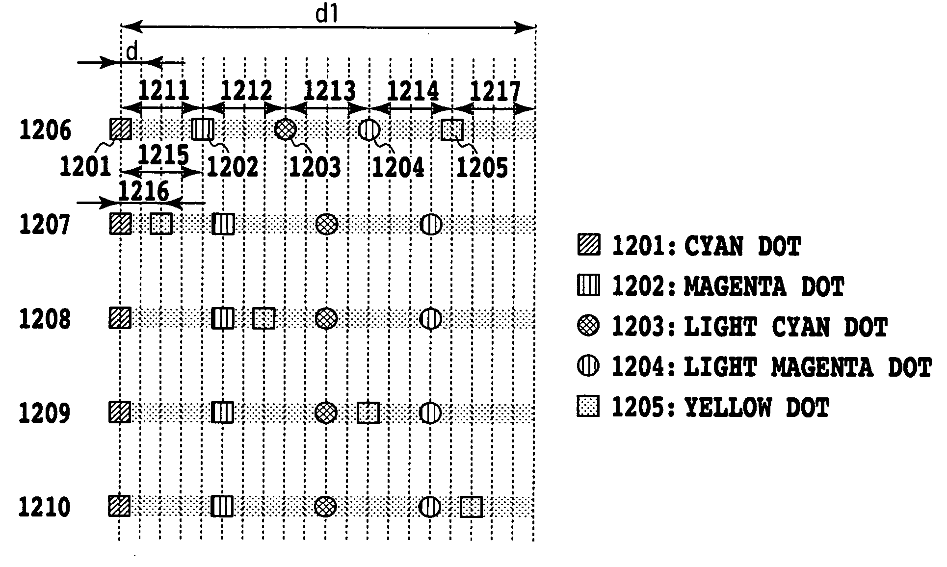
[0057]FIGS. 8A to 8C are diagrams showing patterns of paper preliminary ejection according to a first embodiment of the present invention through dot arrangements formed by ink ejection in pixels. In this embodiment, the preliminary ejection is performed based on the basic pattern of FIG. 7 for respective colors, and such basic patterns are arranged offset so as not to overlay for respective colors, as shown in FIGS. 8A to 8C. To simplify the description, these drawings show the preliminary ejection pattern of inks except for that of black, among patterns of paper preliminary ejection in the ink jet printer which prints by using ink of respective colors: cyan (C), magenta (M), yellow (Y), light cyan (LC), light magenta (LM) and black (K).

[0058]Here, FIGS. 8A to 8C show patterns of paper preliminary ejection in the case that in a printing head where ejection orifice rows of respective ink colors are arranged at the same level in the main scanning direction with an interval of 1 cm as...

second embodiment

[0070]FIG. 9 is diagram showing a pattern of paper preliminary ejection according to a second embodiment of the present invention through dot arrangements, which are formed by the preliminary ejection, in pixels. The present embodiment relates to the paper preliminary ejection pattern in an ink jet printer where cyan (C), magenta (M), yellow (Y) and black (K) are used as ink and, to simplify the description, FIG. 9 shows the preliminary ejection pattern of ink except for black, similarly to the first embodiment mentioned above. Moreover, as shown in the first embodiment mentioned above, the above pattern shows the paper preliminary ejection pattern in the case where one ejection orifice corresponding to one straight line along the main scan direction for each ink, using a printing head of which ejection orifice rows of respective colors of ink are arranged at the same level in the main scanning direction with an interval of 1 cm, scans with scanning speed of 25 inch / sec and ejects w...

third embodiment

[0077]In the aforementioned first and second embodiments, preliminary ejection patterns are described in the case where the quantity (the number of times of ejection) of ink of respective colors is the same in paper preliminary ejection, while the present embodiment relates to a preliminary ejection pattern in the case where the quantity (the number of times of ejection) is differentiated according to the ink color.

[0078]FIG. 10 is a diagram showing a pattern of paper preliminary ejection according to a third embodiment of the present invention. The pattern of the present embodiment shows a pattern of the case where the quantity of preliminary ejection of cyan (C) ink can be more than those of the other colors of ink, and, as a whole the quantity of preliminary ejection of magenta and yellow inks can be reduced. More specifically, compared to the aforementioned second embodiment, a pattern where three cyan dots, one magenta dot and one yellow dot respectively are arranged as a patte...


PUM


Abstract

The image quality deterioration due to the collection of dots of low-lightness by the preliminary ejection is prevented, in the case of performing the ink ejection for preliminary ejection during the printing onto printing paper. More specifically, the preliminary ejection pattern is set as a pattern in which the distance between a cyan dot of relatively low-lightness and a magenta dot is longer than a distance between a yellow dot of relatively high-lightness and a cyan dot nearest the yellow dot among low-lightness colors. Closely forming dots of low-lightness that would be perceived as a group of collected dots can be prevented, thereby performing printing that will not deteriorate the printing quality due to the paper preliminary ejection.

Description

BACKGROUND OF THE INVENTIONField of the Invention[0001]The present invention relates to an ink jet printing method and an ink jet printing apparatus and, more particularly, to an ink jet printing method and an ink jet printing apparatus for performing so-called preliminary ejection, in which ink is ejected from a printing head for taking no part of printing, is performed while printing an image.[0002]Also, the present invention can be applied to apparatuses such as a printer, a copying machine, a facsimile machine having a communication system, a word processor having a printer section and so on for printing on a medium to be printed such as paper, yarn, fiber, fabric, metal, plastic, rubber, glass, wood, ceramics and so on and, moreover, industrial printing apparatuses combined complexly with various processing units.[0003]It should be appreciated that “printing” in the present specification means not only to afford images having a meaning such as characters and graphics to the med...

Claims


Application Information

Patent Timeline
Patent Type & Authority Patents(United States)
IPC IPC(8): B41J2/205B41J2/01B41J2/145B41J2/15B41J2/165B41J2/21
CPCB41J2/2056B41J2/16526B41J2002/16529
Inventor FURUICHI, TOMOMITAKEKOSHI, RIEKANEMATSU, DAIGOROBABA, NAOKOSUZUKI, KAZUONAGAMURA, MITSUTOSHI
Owner CANON KK
Why Eureka
Try Eureka