
Dual purpose mini-charger

a mini-charger and charger technology, applied in the direction of electric vehicles, transportation and packaging, connections, etc., can solve the problems of inconvenience in carrying it outdoors, difficulty in reducing the volume of the whole charger structure, and inconvenient access to the power source, so as to improve the utilization rate of the room, reduce the volume of the charger, and be convenient to carry.

Inactive Publication Date: 2007-11-06
SAMYA TECHNOLOGY CO LTD
View PDF4 Cites 24 Cited by
  • Summary
  • Abstract
  • Description
  • Claims
  • Application Information

AI Technical Summary

Benefits of technology

[0009]It is a primary object of the invention to provide a dual purpose mini-charger in which the opening of the charging groove is formed at both sides thereof, thereby ensuring an excellent room utilization. Meanwhile, the volume of the charger can be reduced to a thin elongated shape. Furthermore, the charger is suitable for charging different secondary batteries. Thus, the charger is easy to carry and meets the requirements of charging two secondary batteries.
[0010]It is another object of the invention to provide a dual purpose mini-charger that avoids a reverse charging process caused by a reverse placement of the secondary batteries in the charging groove, thereby achieving a better safety and prolonging the service life.

Problems solved by technology

The problem of the electronic products using the secondary batteries lies in the inconvenience of access to the power source when the user going out for a business trip uses up the energy in the battery.
Besides, the charging electronic unit 12 is fitted to the bottom of the charging groove 13 so that it is difficult to reduce the volume of the whole structure of the charger 10, thereby causing inconvenience in carrying it outdoors.
It is also a problem that the AC mains socket is usually unavailable outdoors.
As a result, this kind of the USB charger 30 has also the problem of large volume.
In addition, the use of the connection cord 32 is unfavorable for carrying.
Thus, the use of the USB charger 30 is much restricted, too.
This will cause much inconvenience and occupy much space.

Method used


Image

  • Dual purpose mini-charger
  • Dual purpose mini-charger
  • Dual purpose mini-charger

Examples


Embodiment Construction

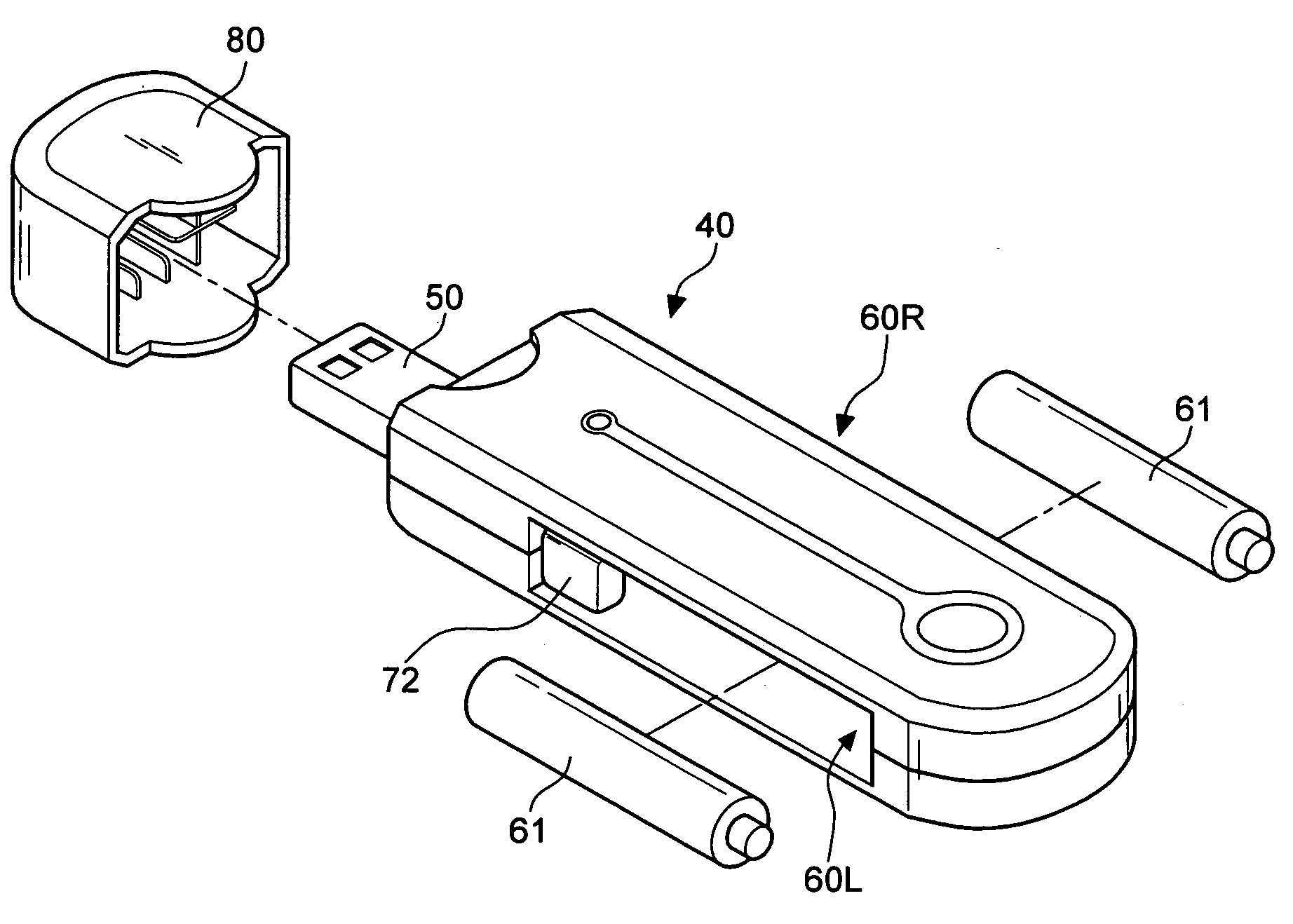
[0029]First of all, referring to FIGS. 3 through 5, a preferred embodiment of the invention includes a main charging body 40. The main charging body 40 has a USB-plug 50 at the front end thereof. The USB-plug 50 is connected to a USB-socket (not shown) for obtaining the direct current from the USB-socket. The main charging body 40 consists of an upper and a lower housing 41, 42 in which a receiving chamber 43 is formed for accommodating a charging control circuit board 70.

[0030]The main charging body 40 has a left and a right charging groove 60L, 60R at both sides thereof for the insertion of Ni—MH (nickel-metal hydride) or NiCd (nickel-cadmium) secondary batteries 61 for the charging purpose. Moreover, the left and right charging grooves 60L, 60R are disposed in an axial direction with respect to the USB-plug 50 in such a way that they are formed in a slim shape. Meanwhile, the opening is directed outwards for facilitating the removal and insertion of the secondary batteries 61. In...


PUM


Abstract

A dual purpose mini-charger includes: a main charging body having a USB-plug at the front end thereof, the USB-plug being connected to a USB-socket for obtaining the direct current for the charging purpose; two charging grooves adapted to accommodate batteries, the left and right charging grooves being disposed at both sides of the main charging body in an axial direction with respect to the USB-plug; and a charging control circuit board having a front portion adapted to fix a plurality of connecting pins in place such that an electric connection is created, the charging control circuit board further having a rear portion to which two pieces of first terminals are electrically coupled, the first terminals each having a contact piece fitted to an indentation at the bottom end of the left and right charging grooves, a second terminal with the telescopic and conducting function being disposed at an end opposite to the first terminals, the external end projecting at the front end of the charging groove. In this way, a secondary battery charger is small and suitable for charging two types of secondary batteries.

Description

BACKGROUND OF THE INVENTION[0001]1. Field of the Invention[0002]The invention relates to a Ni—MH (nickel-metal hydride) or NiCd (nickel-cadmium) secondary battery charger, and more particularly, to a charger with charging grooves at both sides thereof. Moreover, the charger is suitable for charging different types of batteries.[0003]2. Description of the Related Art[0004]With the popularity of portable electronic products like digital cameras, MP3, PDA, etc., the demand for secondary batteries is considerably raised. The problem of the electronic products using the secondary batteries lies in the inconvenience of access to the power source when the user going out for a business trip uses up the energy in the battery.[0005]As shown in FIGS. 1A and 1B, a charger 10 includes a plug 11 at the bottom thereof. The plug 11 is adapted to insert into an AC mains. A charging electronic unit 12 is disposed within the charger 10. The charging electronic unit 12 includes a positive and a negativ...

Claims


Application Information

Patent Timeline
IPC IPC(8): H02J7/00
CPCH02J7/0042
Inventor YANG, FU-I
Owner SAMYA TECHNOLOGY CO LTD
Learn More