[0013]Disclosed is a modular
distraction screw and a rod-based
bone fixation system. The distraction screw is placed as the first step of
surgery when all relevant landmarks are still intact and used for the bone work prior to
device placement. After completion of the bone work, a proximal end of the distraction screw is detached, leaving one or more distal segments still implanted in the upper-most and lower-most vertebral bodies. The distal segments are used to guide the
bone fixation device into the correct placement position and serve to hold it stationary while the
bone screws are placed. Since the distraction screws were placed with intact surgical landmarks, use of the distal segments to guide the device significantly increases the likelihood of its proper placement. In addition, this
placement method leaves no empty bone holes to serve as
stress concentration points and further weaken the vertebral bodies.
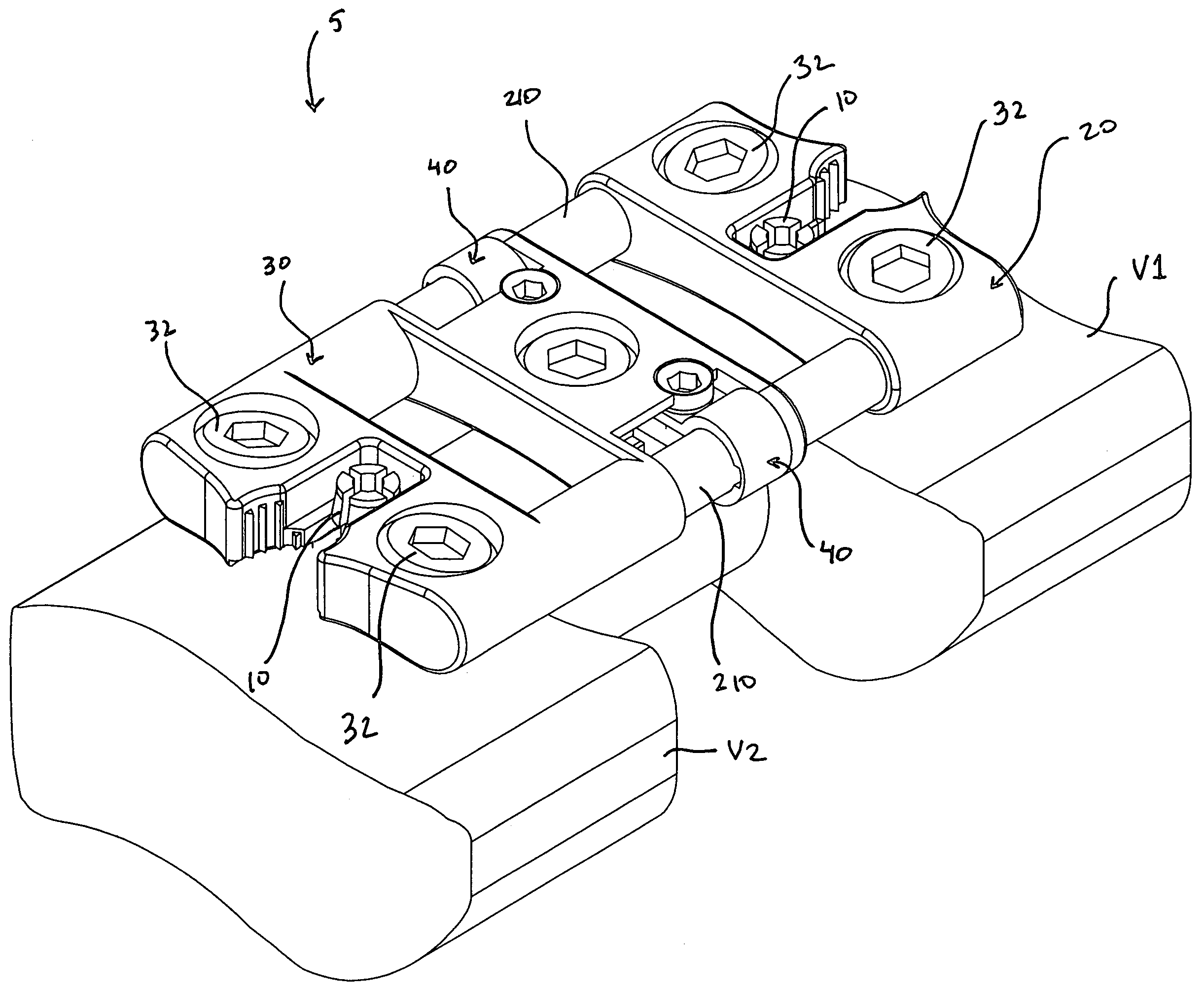
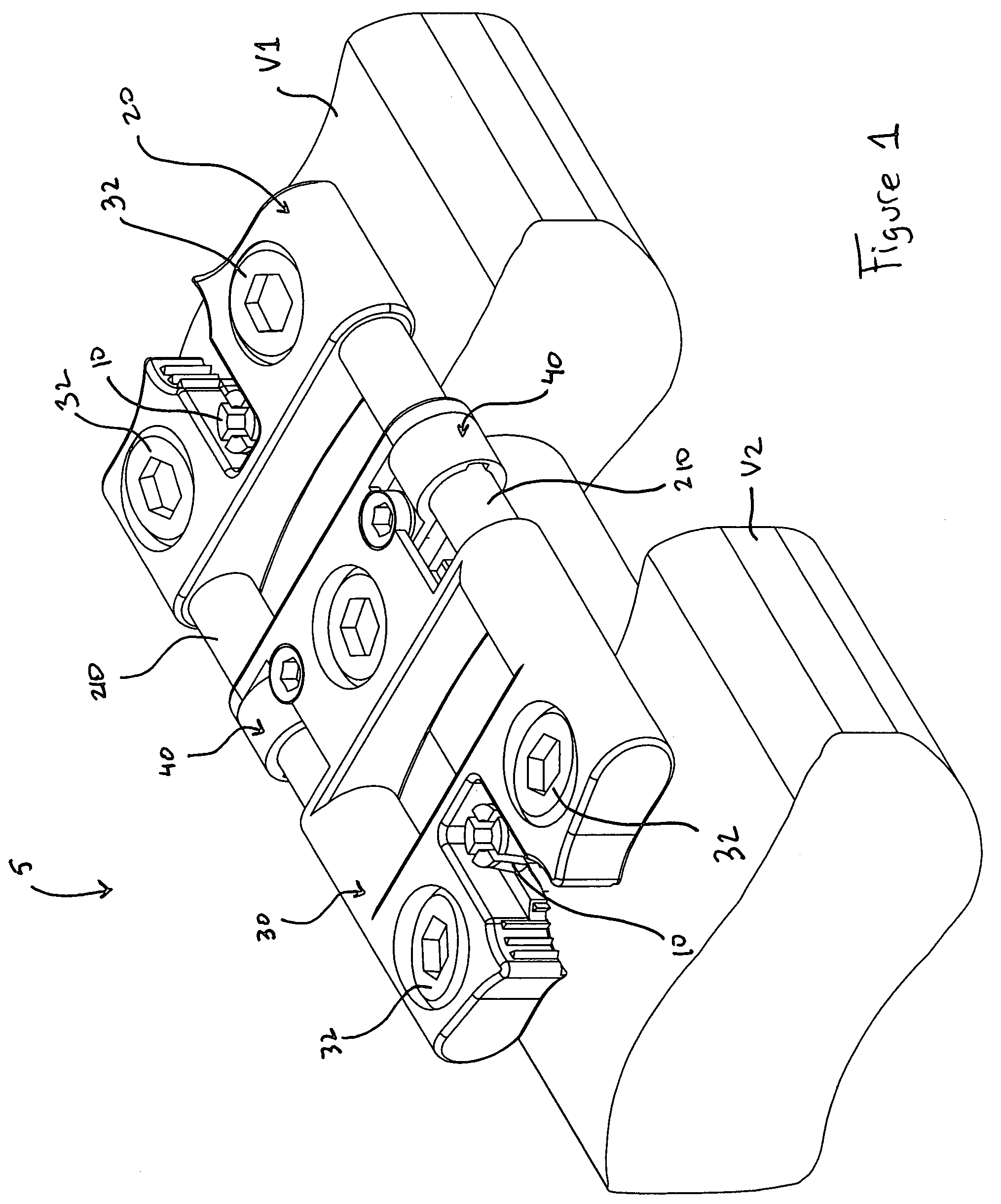
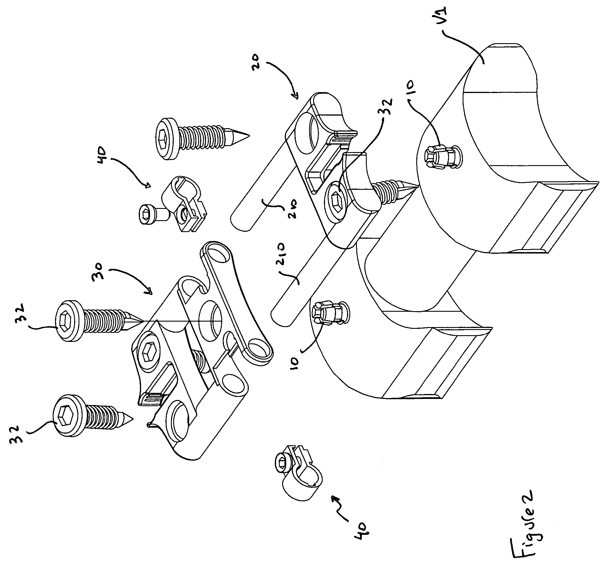
[0014]In one embodiment, the bone fixation device includes two sliding components, with one component rigidly affixed onto the
vertebral body above the fused space and the other affixed onto the vertebra below. The rod-based sliding segment of each sliding component permits movement along the longitudinal axis of the spine but limits movement in all other planes. A third component comprised of an adjustor component is used to control the range of motion between the first and second sliding components. The relationship between the third, adjustor component and one of the sliding components will determine the extent of variation permitted in the fixation device's overall length. The third component can be locked or unlocked to control the range of motion. When the third component is locked, movement between it and the second sliding component determines the extent of bony
subsidence permitted. These design features collectively allow development of a
variable length rod-based fixation device that is capable of accommodating bony
subsidence at the level of the
settling bone, and not at the end of the device.
[0015]A modular coupler is placed at either end of the device, permitting extension of the fusion at a later date without
device removal. The extension is started by connecting a modified distraction screw to the coupler at the end of the device immediately adjacent to the disc to be removed. A modular distraction screw is inserted into the
vertebral body on the other side of the diseased
disc space. Alternately, a conventional, one-piece distraction screw (rather than the modular distraction screw described herein) can be used to distract the vertebra during
discectomy. The distraction screws are then used to distract and open the intervening
disc space. A
discectomy and subsequent fusion are performed within that
disc space. After completion of the bone work, the modified distraction screw is removed leaving the bare coupler on the end of the fixation device. The proximal segment of the distraction screw is also removed leaving the
distal segment attached to the adjacent
vertebral body. An extension device is used to span the space between the
distal segment of the distraction screw on the adjacent vertebra and the end-coupler on the
original device. In this way, the fusion is extended and the newly fused segment is fixated without removal of the original fixation device. Further, the end-coupler can used to correct any improper (“crooked”) placement of the original plate by rotating the extension piece into the true vertical.
[0016]The rod-based bone fixation
system described herein provides ease of use, reliable bone fixation,
modular design,
accommodation of bone
settling, and the ability to interact with an implantable distraction screw. These designs maximize the likelihood of proper
device placement, avoid maneuvers that weaken the vertebral bodies, address all shortcomings enumerated above, and provide a substantial
advantage over the current and prior art.

