Cyclonic separating apparatus

a cyclonic separation and separating device technology, applied in the direction of liquid separation agent, filter regeneration, dispersed particle filtration, etc., can solve the problems of reduced flow, reduced separation efficiency, and increased so as to prevent blockage, reduce the risk of cyclone blockage, and optimise separation performance

Active Publication Date: 2007-11-06
DYSON TECH LTD
View PDF16 Cites 32 Cited by
  • Summary
  • Abstract
  • Description
  • Claims
  • Application Information

AI Technical Summary

Benefits of technology

[0005]It is an object of the present invention to provide cyclonic separating apparatus in which the risk of blockage of a cyclone is reduced.
[0006]The invention provides cyclonic separating apparatus comprising at least one cyclone, the cyclone having a first end and a second end, an inlet being located at the first end for introducing a fluid flow into the cyclone, a cone opening being located at the second end, the cyclone further comprising a longitudinal axis, wherein at least part of the cone opening lies in a plane inclined at an angle to the longitudinal axis. The configuration of the cone opening provides a greater area for the dirt to pass through which helps to prevent blockages occurring in the cyclone.
[0007]Preferably, the plane is inclined at an angle of between 40° and 80° to the longitudinal axis. More preferably, the plane is inclined at an angle of substantially 60° to the longitudinal axis. It has been found that at this angle cone blocking is less likely to occur and there is no increased risk of the separated dust being re-entrained.
[0008]In a preferred embodiment, the cyclone projects into the collector. This enables any dust which has been separated from the flow to be contained and so prevented from passing into the surrounding atmosphere. The contained dust can then be emptied from the collector in a safe and hygienic manner. Preferably, the collector has a portion having a substantially circular cross section, the diameter of the said portion being at least three times the diameter of the cone opening. More preferably, the said portion lies in a plane which intersects the cone opening. In this configuration, the separation performance may be optimised and the dust collected more efficiently.
[0009]The invention is particularly suited to use with a plurality of cyclones. The effect of passing the dust laden flow through a plurality of cyclones arranged in parallel is to enhance the separation efficiency of the apparatus. It is an advantage to have all of the cyclones communicating with a single collector to ensure that all of the dust separated from the flow can be disposed of easily and efficiently.
[0010]In this case, it is preferred that the cone opening has a lowermost portion which extends furthest from the first end of the cyclone and the said lowermost portion faces the wall of the collector. In this orientation, it is believed that separation of the entrained dust is optimised and the risk of cone blocking is reduced.

Problems solved by technology

Cyclones can be prone to blocking.
In particular, small cyclones are more likely to become blocked because there is a smaller area for the dust to pass through.
Such blockages can cause a reduction in flow which has the overall effect of reducing the separation efficiency.
A substantial blockage may completely stop the flow from passing through the cyclone.

Method used


Image

  • Cyclonic separating apparatus
  • Cyclonic separating apparatus
  • Cyclonic separating apparatus

Examples


first embodiment

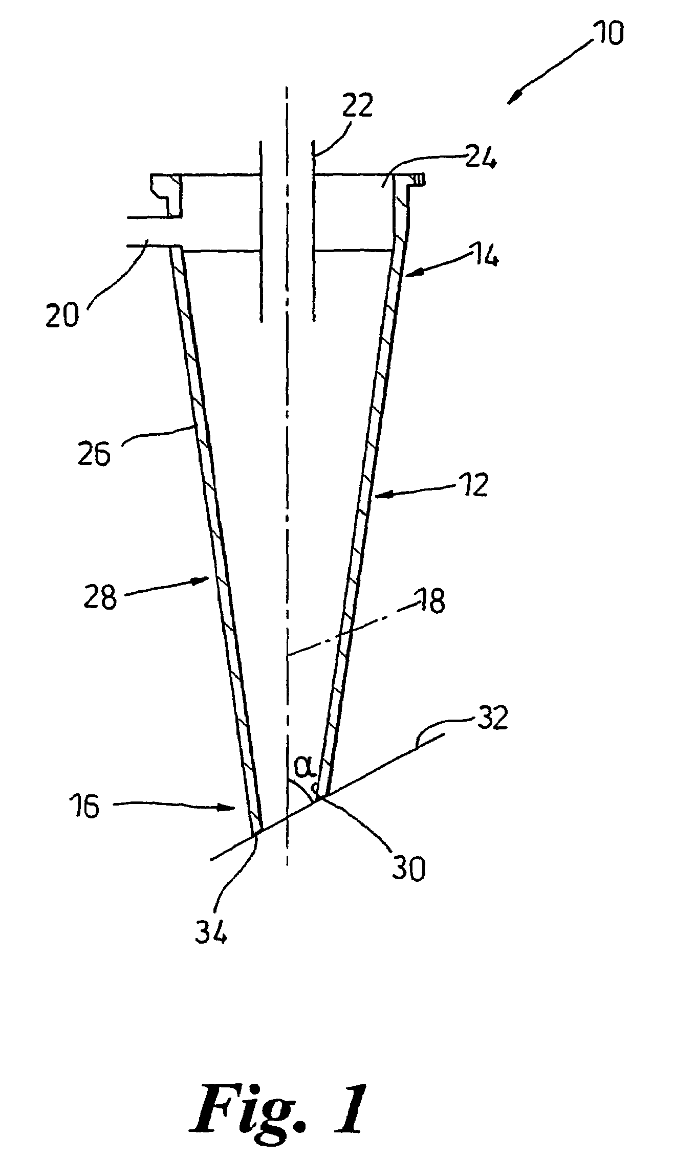
[0018]FIG. 1 shows cyclonic separating apparatus 10 according to the invention. The cyclonic separating apparatus 10 comprises a cyclone 12 having a first end 14, a second end 16 and a longitudinal axis 18. The first end 14 is generally cylindrical and has an inlet 20 for introducing dust laden fluid, preferably air, into the cyclone 12. The inlet 20 is circular in cross-section and communicates tangentially with the first end 14. An outlet 22 is also provided at the first end 14 to direct cleaned air out of the cyclone 12. The outlet 22 lies on the longitudinal axis 18 and extends from the interior of the cyclone 12 and through an upper portion 24 of the first end 14.

[0019]A side wall 26 tapers inwardly towards the longitudinal axis 18 from the first end 14 towards the second end 16 to form a frusto-conical portion 28. A cone opening 30 is formed at a free end of the frusto-conical portion 28. The cone opening 30 lies in a plane 32 inclined at an angle α to the longitudinal axis 18...

second embodiment

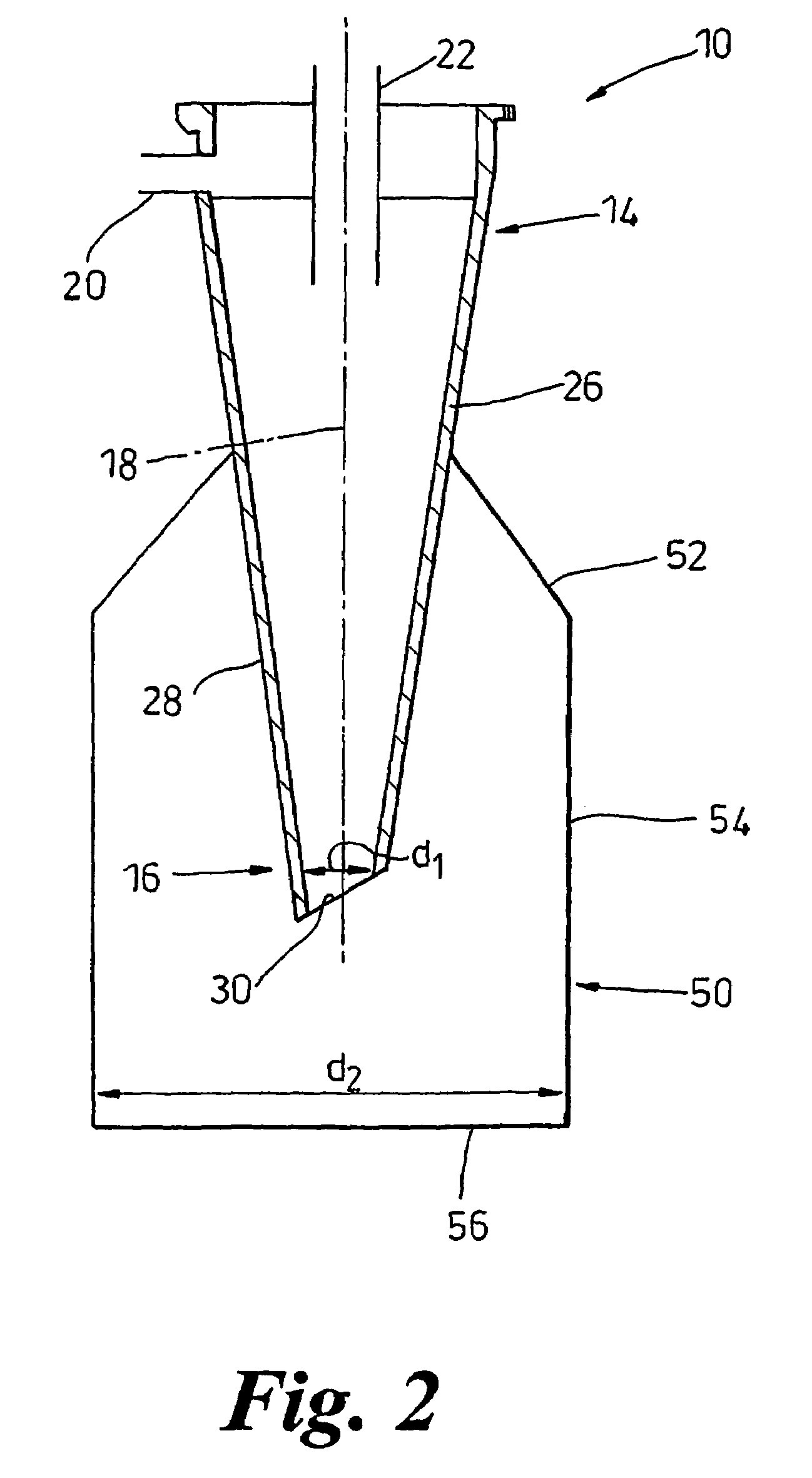
[0020]In a second embodiment, shown in FIG. 2, the cone opening 30 projects into a collector 50. The cyclonic separating apparatus 10 is otherwise the same as that shown in FIG. 1. The collector 50 comprises a frusto-conical upper portion 52 and a cylindrical body portion 54 which is closed by a circular base 56. The upper portion 52 abuts against the side wall 26 of the cyclone 12. The diameter d2 of the circular base 56 is at least three times the projected diameter d1 of the cone opening 30. The diameter d2 shown in FIG. 2 is approximately six times the diameter d1. To minimise any possibility of particle re-entrainment, the cone opening 30 is spaced from the body portion 54 and from the circular base 56.

[0021]In use, a dust-laden fluid flow enters the separating apparatus 10 via the inlet 20. The fluid flow is caused to follow a helical path around the interior of the cyclone 12 from the first end 14 downwardly towards the second end 16 and through the cone opening 30. The frust...

fourth embodiment

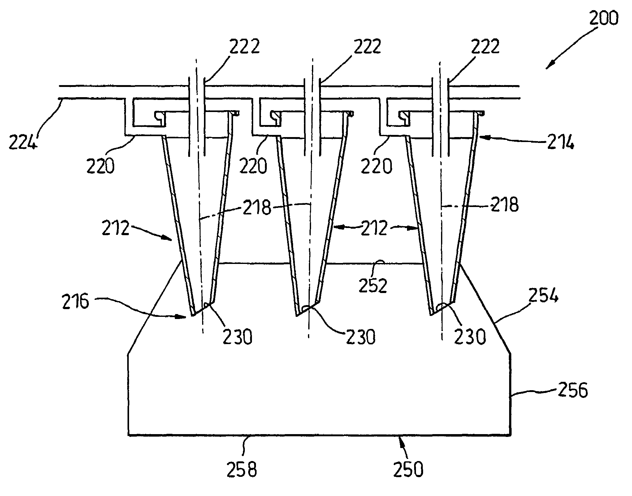
[0023]the invention is shown in FIG. 4. The separating apparatus 200 comprises an arrangement of parallel cyclones 212 each having the same configuration as the cyclone 12 of FIG. 1. It will be appreciated that the cyclones 212 could alternatively have the configuration of the cyclone 112 shown in FIG. 3. The cyclones 212 are arranged so as to lie alongside one another, each having a tangential inlet 220 and an outlet 222. A main inlet 224 feeds dust laden fluid flow into the separating apparatus 200 and a proportion of the fluid flow is directed into each inlet 220. Each cyclone 212 has a cone opening 230 which projects into a common collector 250 having an upper portion 252, tapering side walls 254, a cylindrical body 256 and a base portion 258. The cone opening 230 of each cyclone 212 lies in a plane which is inclined to the longitudinal axis 218 of the respective cyclone 212.

[0024]A specific arrangement of parallel cyclones is shown in FIGS. 5 and 6. Twelve cyclones project into...


PUM

PropertyMeasurementUnit
angleaaaaaaaaaa
angleaaaaaaaaaa
angleaaaaaaaaaa

Abstract

A cyclonic separating apparatus includes at least one cyclone having a first end, a second end a longitudinal axis. An inlet is located at the first end for introducing a fluid flow into the cyclone, and a cone opening is located at the second end. At least part of the cone opening lies in a plane inclined at an angle to the longitudinal axis

Description

FIELD OF THE INVENTION[0001]The invention relates to cyclonic separating apparatus. Particularly, but not exclusively, the invention relates to cyclonic separating apparatus suitable for use in a vacuum cleaner.BACKGROUND OF THE INVENTION[0002]Cyclonic separating apparatus is known, for example, from EP 0 042 723 and U.S. Pat. No. 5,160,356. Both examples show domestic vacuum cleaners which operate using reverse flow cyclones to achieve particle separation. Such apparatus generally provides a cyclone body having a tangential inlet. Dirt-laden fluid flow enters the inlet and follows a helical path around the interior of the cyclone body. Centrifugal forces act on the entrained dirt to separate the dirt from the flow. The separated dirt collects at the base of the cyclone body for subsequent removal from the apparatus. The cleaned flow then changes direction and flows back up the cyclone body to exit the cyclone body via a centrally located outlet provided at the same end of the cyclo...

Claims


Application Information

Patent Timeline
Patent Type & Authority Patents(United States)
IPC IPC(8): B01D45/12A47L9/16B04C5/08B04C5/14B04C5/185B04C5/28
CPCA47L9/1641A47L9/1658B04C5/08B04C5/185B04C5/28B04C5/14Y10S55/03
Inventor DUMMELOW, ANTHONY JOSEPHHARRIS, DAVID STUARTGOMICIAGA-PEREDA, RICARDO
Owner DYSON TECH LTD
Why Eureka
Try Eureka