Entangled photon fourier transform spectroscopy

a fourier transform and entangled photon technology, applied in the field of spectroscopy, can solve the problems of limited frequency information range of existing spectrometers, limited performance and sensitivity, and difficult access to far-ir and thz frequency bands with conventional absorption spectroscopy, and achieve high resolution

Inactive Publication Date: 2007-11-06
MDA INFORMATION SYST
View PDF39 Cites 25 Cited by
  • Summary
  • Abstract
  • Description
  • Claims
  • Application Information

AI Technical Summary

Benefits of technology

[0009]Entangled-photon spectrometer embodiments according to the present invention substantially overcome the aforementioned limitations. Biphotons can be generated such that the signal and idler beams have different center frequencies, which presents the possibility of performing spectroscopy in the far-IR and THz frequency bands that are otherwise difficult to access. Moreover, such novel embodiments disclosed herein use off-the-shelf dispersive elements designed for visible or near-IR bands. Further, embodiments of the present invention are resistant to background radiation, which makes possible the use of entangled-photon spectroscopy over very long distances, e.g., for identification of atmospheric contaminants. Existing long-distance sensors are typically limited to a few narrow frequency bands using lasers that may pose environmental hazards. In contrast, the light levels required for embodiments of the present invention are completely benign and neither degrade the sample of interest nor pose an environmental hazard. Entangled-photon spectrometer embodiments according to the present invention are insensitive to re-radiated energy. For electronic coincidence counter embodiments of the present invention, the sensitivity of the spectrometer can be increased as needed by increasing an easily-manipulated parameter known as integration time. In addition, unlike conventional spectrometers, the only calibration necessary for embodiments of the present invention is a determination of the quantum efficiency of the detector, which can be calibrated by simply removing the sample. That is, an embodiment of the present invention may be calibrated by operating it without a sample present and thereby determining the quantum efficiency of at least one of the detectors. The quantum efficiency of the detector does not change under normal conditions. Because spectrographic information is measured according to embodiments of the present invention in one of two entangled-photon beams, the detector can be positioned to measure reflected or scattered light at any angle by simply moving the detector. Such flexibility in a conventional spectrometer would result in significant increases in the complexity of the device and difficulty in calibration.

Problems solved by technology

First, known spectrometers that employ dispersive elements are quite sensitive to background radiation, which limits their performance and sensitivity.
Second, existing spectrometers are limited in the range of frequency information that they can detect.
In particular, far-IR and THz frequency bands, which are rich in spectroscopic information, are difficult to access with conventional absorption spectroscopy.
Third, calibration of conventional spectrometers requires calibrating the power source at the time of measurement, and fluctuations in power often result in decreased sensitivity.
Fourth, conventional broadband spectrometers require high fluxes that can damage samples.
Fifth, conventional spectrometers afford less versatility in measuring absorption over long distances, such as in analyzing atmospheric species, or in medical applications.
And sixth, conventional spectrometers are sensitive to re-radiated energy, which can be a source of additional noise in the measurement.
Existing long-distance sensors are typically limited to a few narrow frequency bands using lasers that may pose environmental hazards.
Such flexibility in a conventional spectrometer would result in significant increases in the complexity of the device and difficulty in calibration.

Method used


Image

  • Entangled photon fourier transform spectroscopy
  • Entangled photon fourier transform spectroscopy
  • Entangled photon fourier transform spectroscopy

Examples


Embodiment Construction

[0032]The particulars shown herein are by way of example and for purposes of illustrative discussion of the embodiments of the present invention only and are presented in the cause of providing what is believed to be the most useful and readily understood description of the principles and conceptual aspects of the present invention. In this regard, the description taken with the drawings provides a fundamental understanding of the present invention, making apparent to those skilled in the art how the several forms of the present invention may be embodied in practice.

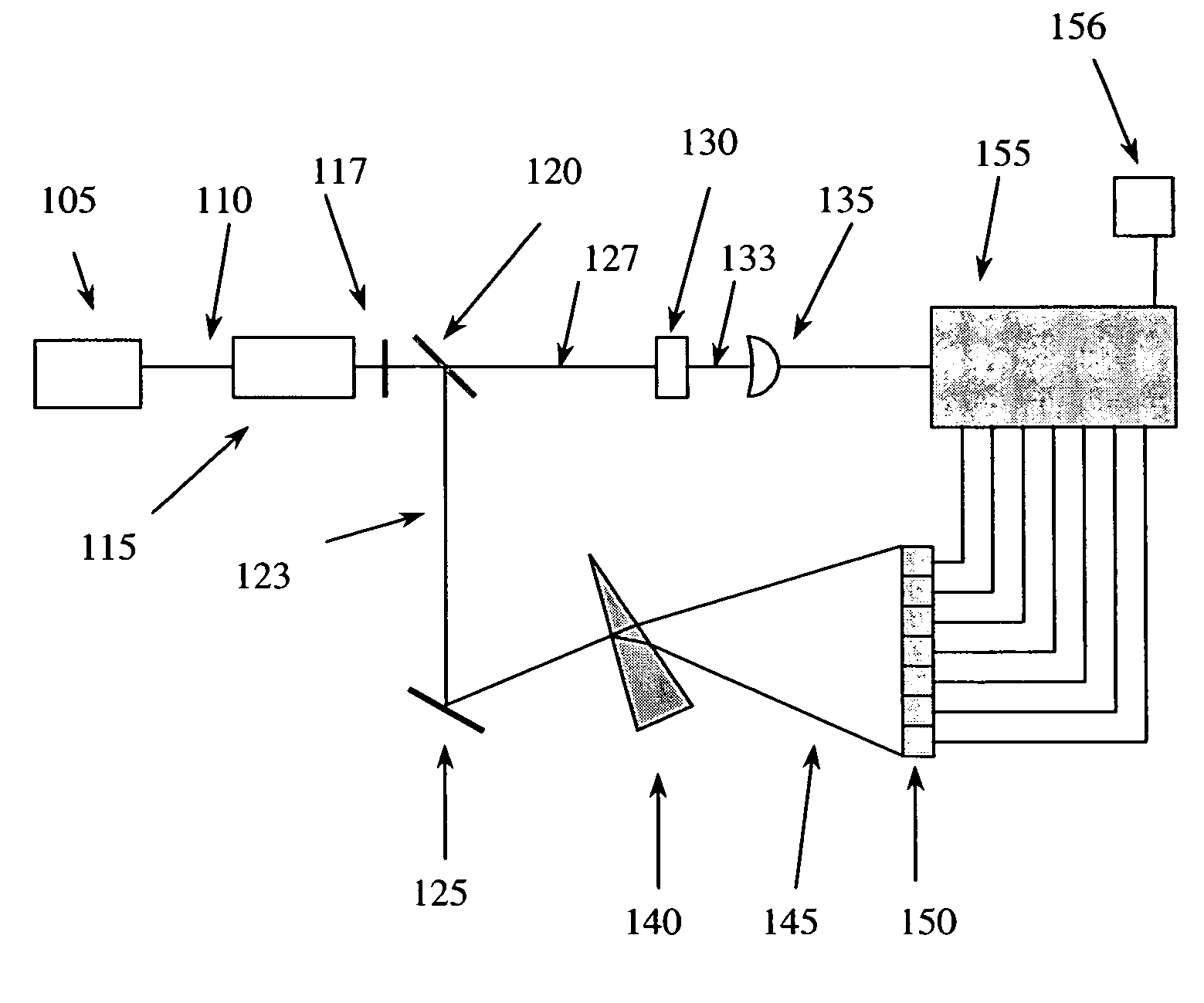
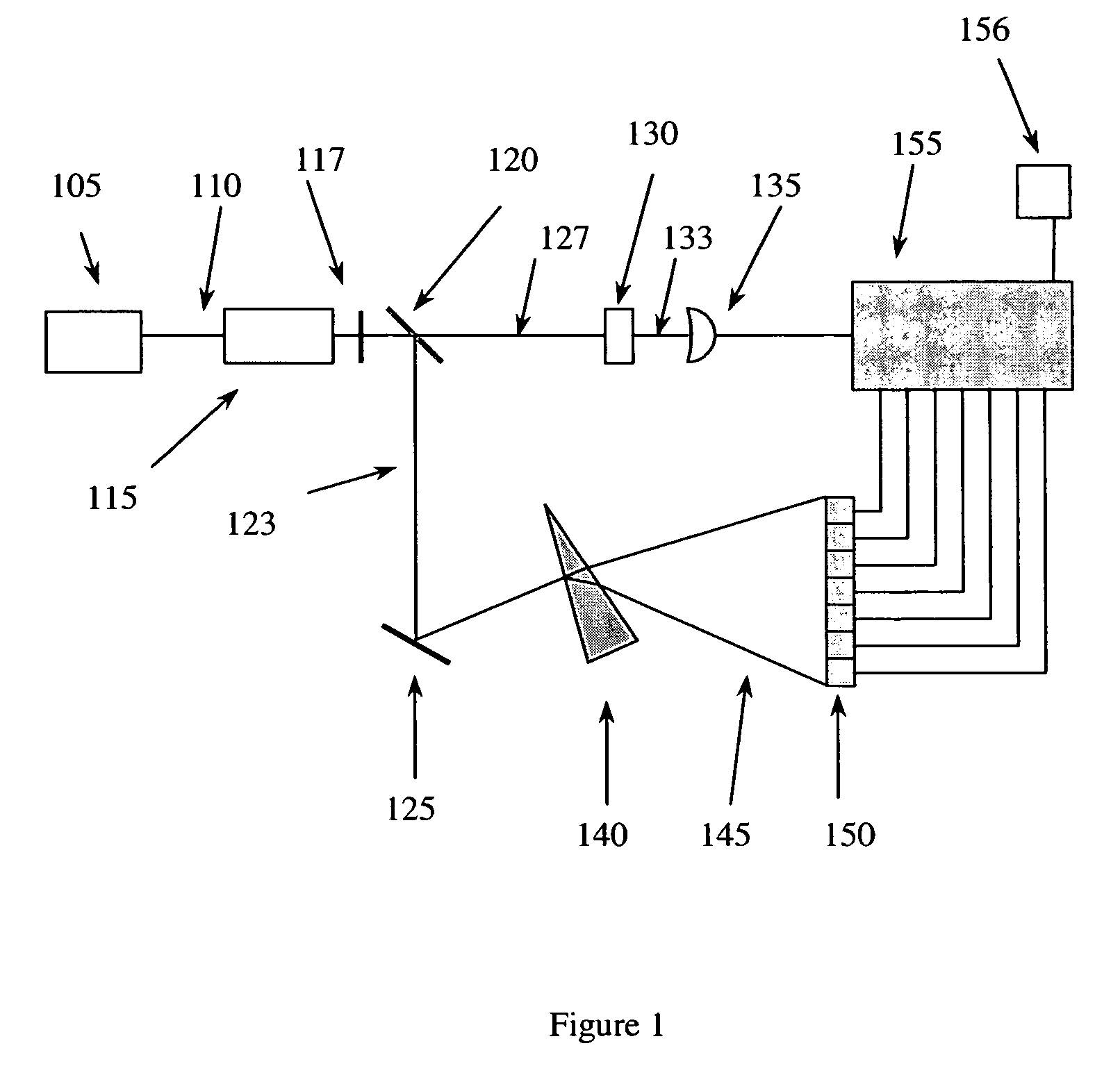
[0033]FIG. 1 is a schematic diagram of an entangled-photon absorption spectrometer embodiment. Pump beam 110 from laser 105 is directed to a nonlinear crystal 115 with a high second-order susceptibility, such as BBO (β-BaB2O4), to produce entangled-photon pairs via parametric downconversion. Filter 117 blocks remaining pump beam photons that may have passed through nonlinear crystal 115. The entangled-photon pairs are th...


PUM

PropertyMeasurementUnit
spectroscopic informationaaaaaaaaaa
frequencyaaaaaaaaaa
quantum efficiencyaaaaaaaaaa

Abstract

Novel spectroscopy techniques using entangled photons are disclosed. In one technique, entangled photons are directed to a sample of interest, while the photons with which they are entangled are resolved according to frequency. The photons transmitted by or reflected from the sample and the frequency-resolved photons are detected. Such detection may be by way of an electronic coincidence counter or a biphoton sensitive material, which absorbs entangled photons while allowing other photon pairs to pass. Detection information is used to derive spectroscopic properties of the sample. In another technique, a Fourier transform spectroscopy technique using entangled photons is disclosed. Entangled photons are directed to a sample, while the photons with which they are entangled are directed to a Michelson interferometer. The photons transmitted by or reflected from the sample and the photons leaving the Michelson interferometer are detected. Such detection may be by way of an electronic coincidence counter or a biphoton sensitive material. Detection information is used to derive spectroscopic properties of the sample.

Description

RELATED APPLICATIONS[0001]The present application claims priority to U.S. Provisional Application Ser. No. 60 / 540,011 entitled “Entangled-photon Fourier Transform Spectrometer” to Zaugg, filed Jan. 30, 2004, and is related to U.S. Utility Application Ser. No. 10 / 850,394 entitled “System and Method of Detecting Entangled Photons” to Kastella et al., filed May 21, 2004, the disclosures of which are expressly incorporated by reference herein in their entireties.FIELD OF THE INVENTION[0002]The present invention relates to spectroscopy. In particular, the present invention relates to absorption spectroscopy using entangled photons.BACKGROUND OF THE INVENTION[0003]Techniques for performing spectroscopy are known. In many of these techniques, light from a broadband source, (e.g., a tungsten filament lamp), impinges upon a sample and is then separated into spectral components via a prism or grating. The prism or grating is rotated to bring each spectral component in turn into a detector whe...

Claims


Application Information

Patent Timeline
Patent Type & Authority Patents(United States)
IPC IPC(8): G01B9/02G01J3/453G01N21/35G02B6/122G02B6/34
CPCB82Y20/00G01J3/453G02B6/1225G02B6/2935G02B6/29349G01N21/3581
Inventor ZAUGG, THOMAS
Owner MDA INFORMATION SYST
Why Eureka
Try Eureka