
Collapsible core assembly for a molding apparatus

a molding apparatus and collapsible core technology, applied in the field of collapsible cores, can solve the problems of high manufacturing cost, difficult to manufacture cores, and suffer drawbacks, and achieve the effects of improving quality and reliability, precise tolerances, and reducing manufacturing costs

Active Publication Date: 2007-11-13
ZYDRON GARRY
View PDF13 Cites 36 Cited by
  • Summary
  • Abstract
  • Description
  • Claims
  • Application Information

AI Technical Summary

Benefits of technology

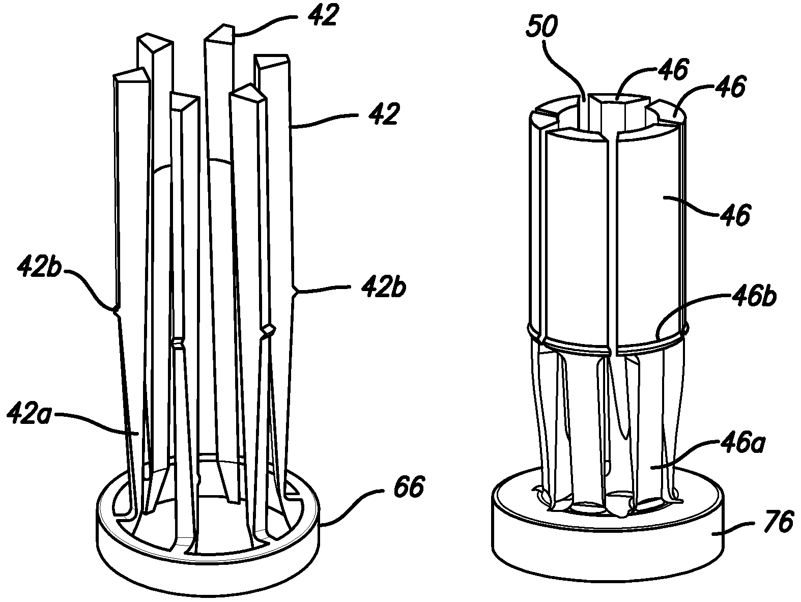
"The present invention provides a collapsible core device for molding articles around a central channel. The core device includes a first sleeve, a second sleeve, and an expansion member. The first sleeve has a plurality of first ribs and a discontinuous first perimeter surrounding a channel. The second sleeve has a plurality of second ribs and a discontinuous second perimeter surrounding the central channel. The expansion member is forcibly fit within the central channel to displace the first and second ribs outwardly and form an overall perimeter defined by the first and second ribs. The invention improves the manufacturability of the collapsible sections of molding apparatus, reduces manufacturing costs, and allows for standard, interchangeable components. The invention also allows for the use of standardized parts and the ability to use alternate pins for increased molded part detail on the core."

Problems solved by technology

The present inventor has recognized that the core as described in the aforementioned patent suffers the drawback that the core is expensive and difficult to manufacture.

Method used


Image

  • Collapsible core assembly for a molding apparatus
  • Collapsible core assembly for a molding apparatus
  • Collapsible core assembly for a molding apparatus

Examples


Embodiment Construction

[0046]While this invention is susceptible of embodiment in many different forms, there are shown in the drawings, and will be described herein in detail, specific embodiments thereof with the understanding that the present disclosure is to be considered as an exemplification of the principles of the invention and is not intended to limit the invention to the specific embodiments illustrated.

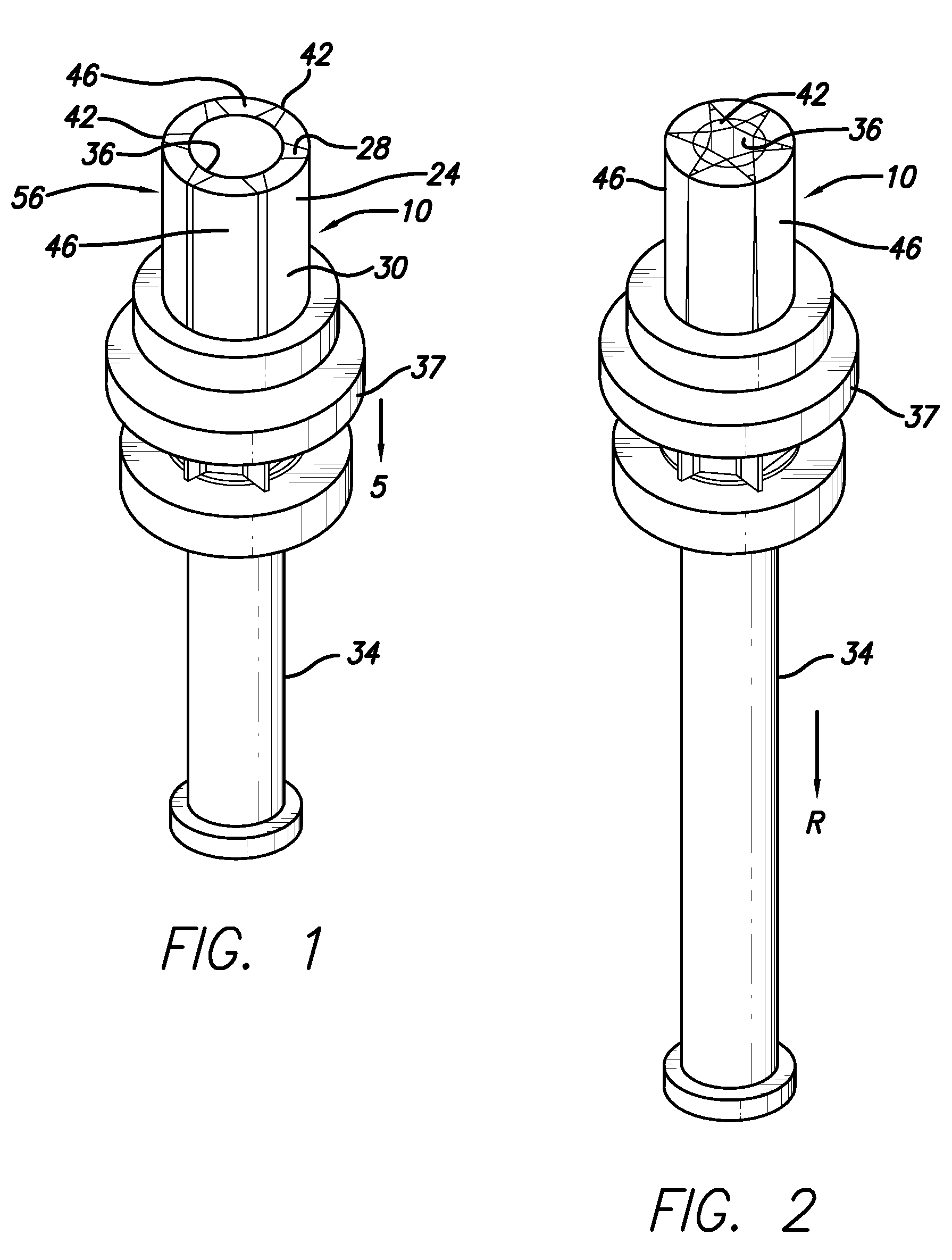
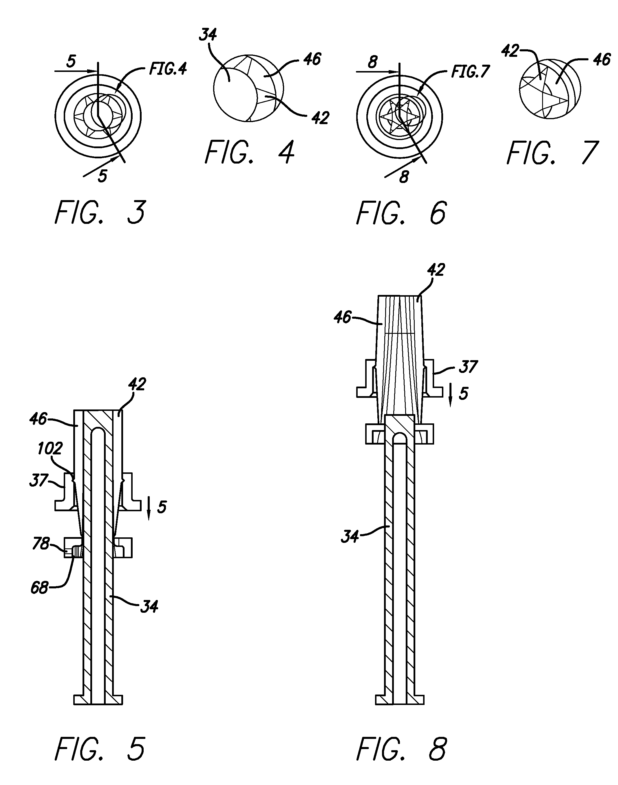
[0047]FIGS. 1-8 illustrate a collapsible core device 10 in accordance with the present invention. The core 10 is used in conjunction with a female mold part 16 as shown schematically in FIG. 17.

[0048]The core device 10 includes a first, outer discontinuous sleeve 24, fit substantially within an outer perimeter 30 of the outer discontinuous sleeve 24. The second discontinuous sleeve 28 is fit within a central channel 32 of the outer discontinuous sleeve 24. A hollow pin 34 is fit within a central channel 36 of the inner discontinuous sleeve 28. A collar 37 surrounds the sleeves 24, 28.

[0049]The in...


PUM

PropertyMeasurementUnit
perimeteraaaaaaaaaa
resiliencyaaaaaaaaaa
resilientaaaaaaaaaa

Abstract

A collapsible core device for molding articles around the core device in a mold cavity includes a first sleeve, a second sleeve and an expansion member. The first sleeve includes a plurality of first ribs extending from a first base in an axial direction and defining a discontinuous first perimeter surrounding a channel. The second sleeve includes a plurality of second ribs extending from a second base in an axial direction and defining a discontinuous second perimeter surrounding the central channel. Each of the second ribs is arranged between adjacent ones of the first ribs. The expansion member is fittable within the central channel to displace the first and second ribs outwardly to form an overall perimeter defined by the first and second ribs.

Description

[0001]This application is a continuation-in-part of U.S. Ser. No. 10 / 906,413, filed Feb. 18, 2005 now abandoned.TECHNICAL FIELD OF THE INVENTION[0002]This invention relates in general to part of an injection mold which produces parts requiring details such as internal threads, undercuts, protrusions, or cut-outs. Particularly, the present invention relates to collapsible cores that are configured to change from an expanded condition to mold an article on the core, to a collapsed condition that allows the article to be removed from the core.BACKGROUND OF THE INVENTION[0003]Collapsible cores have been manufactured for many years, as shown in U.S. Pat. No. 3,247,548. This patent discloses a collapsible core for molding threaded container caps. According to this patent, a one-piece core is longitudinally divided into a plurality of circumferentially disposed sections. The sections include inner and outer ribs that are formed into a common base. The sections are resilient in a radial dir...

Claims


Application Information

Patent Timeline
Patent Type & Authority Patents(United States)
IPC IPC(8): B23P11/02B21D39/00
CPCB29C45/4421Y10T29/49938Y10T29/4987
Inventor ZYDRON, GARRY
Owner ZYDRON GARRY
Learn More