Directional flooding method in wireless sensor network

a wireless sensor and wireless sensor technology, applied in data switching networks, frequency-division multiplexes, instruments, etc., can solve the problems of network falling into a severe contention state, nodes with very limited energy and computing resources, and high cost, so as to reduce the whole energy consumption and avoid unnecessary packet transmission

Active Publication Date: 2007-11-13
AJOU UNIV
View PDF13 Cites 56 Cited by
  • Summary
  • Abstract
  • Description
  • Claims
  • Application Information

AI Technical Summary

Benefits of technology

[0023]Accordingly, the present invention has been made in view of the above problems, and it is an object of the present invention to allow flooding of a packet to be accomplished in the direction that approaches a destination node based on directional information. It is therefore possible to obviate transmission of unnecessary packets and to reduce the whole energy consumption.

Problems solved by technology

For example, in the wireless sensor network, a great number of sensor nodes having very limited energy and computing resources are crowded to form a network.
They have a problem that the cost is high.
Thus, if several neighboring nodes broadcast at the same time, the network can fall into a severe contention state.
Broadcasting that is unnecessarily overlapped with this contention state and collision of signals may cause a broadcast storm problem.
However, the method of forming this optimal tree may be improper since unnecessary overhead is generated in the wireless sensor network environment.
Such a simple flooding scheme can transmit the packet very reliably, but requires high cost.
Meanwhile, in the wireless sensor network, it is highly probable that the flooding method for forming this optimal broadcast tree cannot be the most effective flooding method.
This may result in lots of overhead in the number of packets, energy consumption and delay.

Method used


Image

  • Directional flooding method in wireless sensor network
  • Directional flooding method in wireless sensor network
  • Directional flooding method in wireless sensor network

Examples


Embodiment Construction

[0042]The present invention will now be described in detail in connection with preferred embodiments with reference to the accompanying drawings.

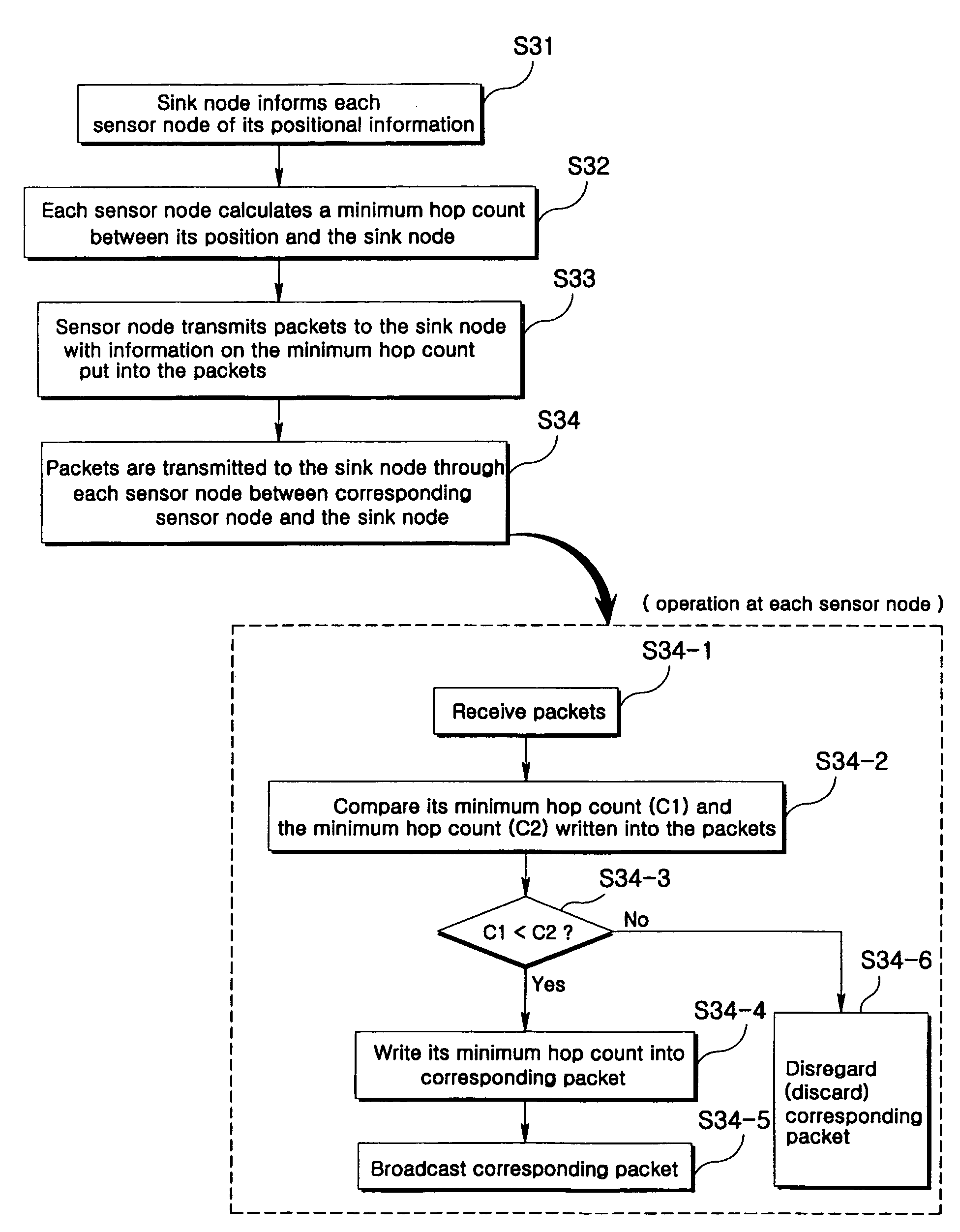
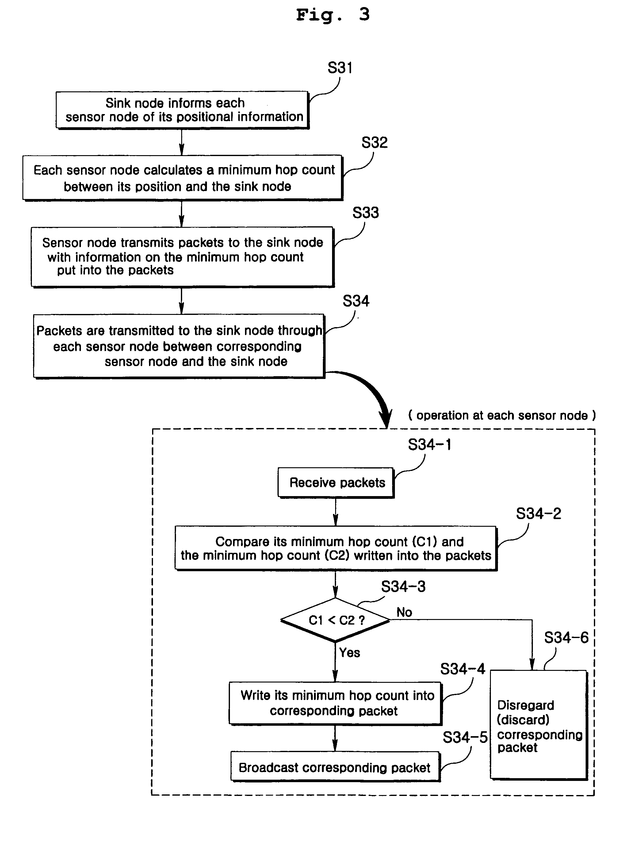
[0043]An embodiment that a packet is transmitted from given sensor nodes to a sink node will be explained with reference to FIG. 3.

[0044]In a flooding method according to the present invention, each of sensor nodes determines whether to flood based on directional information toward a destination node. To this end, it is required that each sensor node be constructed to know its position. For example, the sensor node may use positional information through a GPS receiver.

[0045]A sink node initially informs the respective sensor nodes of its positional information (S31).

[0046]It is assumed that the sink node is rarely moved. Thus, what the sink node informs each sensor node of its positional information can be performed only once when a wireless sensor network is initially formed. Each of the sensor nodes that received the positional informatio...


PUM


Abstract

The present invention relates to a directional flooding method in a wireless sensor network. Transfer of a packet between respective sensor nodes and a sink node in a wireless sensor network is made with the directivity. To this end, when the packet is transmitted from the sensor nodes to the sink node, only the sensor nodes having a minimum hop count for the sink node are involved in transmission of the packet. Meanwhile, if the packet is sent from the sink node to the sensor nodes within a given destination area, after the packet reaches a corresponding destination area, only sensor nodes located within the destination area transmit the packet. The present invention has an effect that it can improve energy consumed on average and a total number of packets transmitted when transmitting the packets in a wireless sensor network compared to a conventional simple flooding method.

Description

BACKGROUND OF THE INVENTION[0001]1. Field of the Invention[0002]The present invention relates to a directional flooding method in a wireless sensor network in which packets transferred between respective nodes are induced toward a destination direction through directional information, thus obviating transmission of unnecessary packets to allow for efficient transmission of the packets.[0003]2. Background of the Related Art[0004]A wireless sensor network recently attracts academic interests due to its several unique characteristics different from a wireless ad hoc network. For example, in the wireless sensor network, a great number of sensor nodes having very limited energy and computing resources are crowded to form a network. Furthermore, each of the sensor nodes usually does not have a global identification such as an IP address.[0005]The wireless sensor network is, however, still considered as a kind of the ad hoc wireless network. This is because the two networks are very simila...

Claims


Application Information

Patent Timeline
Patent Type & Authority Patents(United States)
IPC IPC(8): H04J1/16H04H20/00
CPCH04L45/18H04W40/02H04L45/32H04W84/18H04W40/20
Inventor CHOI, JONG MUKIM, JAI HOONKO, YOUNG BAE
Owner AJOU UNIV
Why Eureka
Try Eureka