Method and a system for monitoring the transmission of optical signals

a technology of optical signals and transmission methods, applied in the field of methods and systems for monitoring the transmission of optical signals, can solve problems such as chromatic dispersion, and achieve the effect of simple and economical

Inactive Publication Date: 2007-11-13
RPX CORP
View PDF7 Cites 6 Cited by
  • Summary
  • Abstract
  • Description
  • Claims
  • Application Information

AI Technical Summary

Benefits of technology

[0011]The present invention aims to provide a monitoring method constituting a simple and economical way of supervising an optical transmission network and monitoring the QoS band by band.
[0016]Said detection step is advantageously carried out by detecting said monitoring signal in the modulated multiplex. This is because it may be useful to recover the monitoring signal when the channels are still in the band. Moreover, because all the channels are overmodulated at the same time, synchronization is not necessary.
[0019]It is therefore also possible to recover the monitoring signal on only one of the channels, after splitting the band into different channels, since each of the channels carries the same monitoring signal.
[0020]An implementation of the method includes a step of canceling said monitoring signal by suppressing said modulation. This is beneficial in terms of being able to modify the monitoring signal.

Problems solved by technology

It should be noted that because this simultaneous modulation is applied to a plurality of carrier waves with different wavelengths, a problem could arise after transmission in links where the media are subject to chromatic dispersion.

Method used


Image

  • Method and a system for monitoring the transmission of optical signals
  • Method and a system for monitoring the transmission of optical signals
  • Method and a system for monitoring the transmission of optical signals

Examples


Embodiment Construction

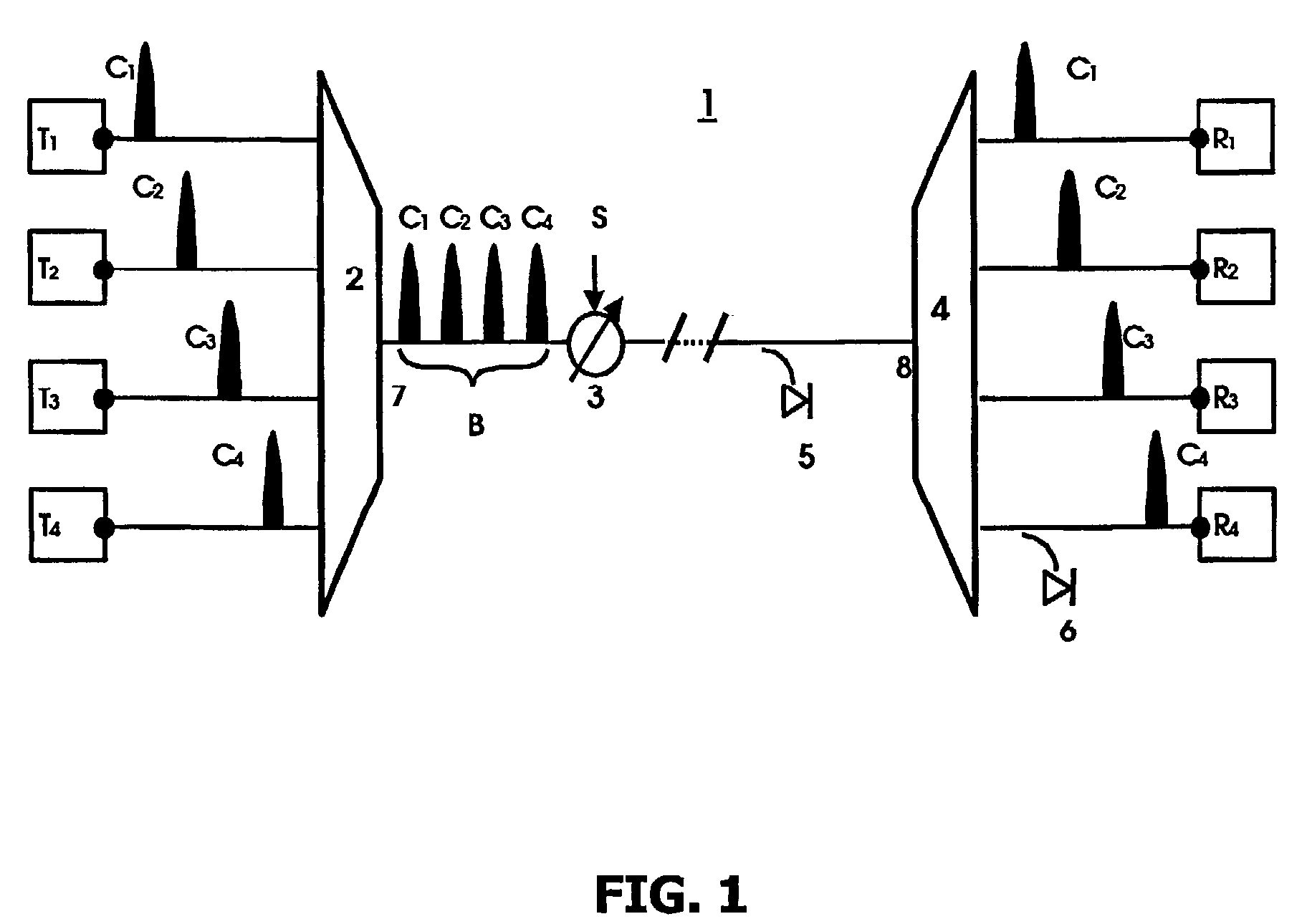
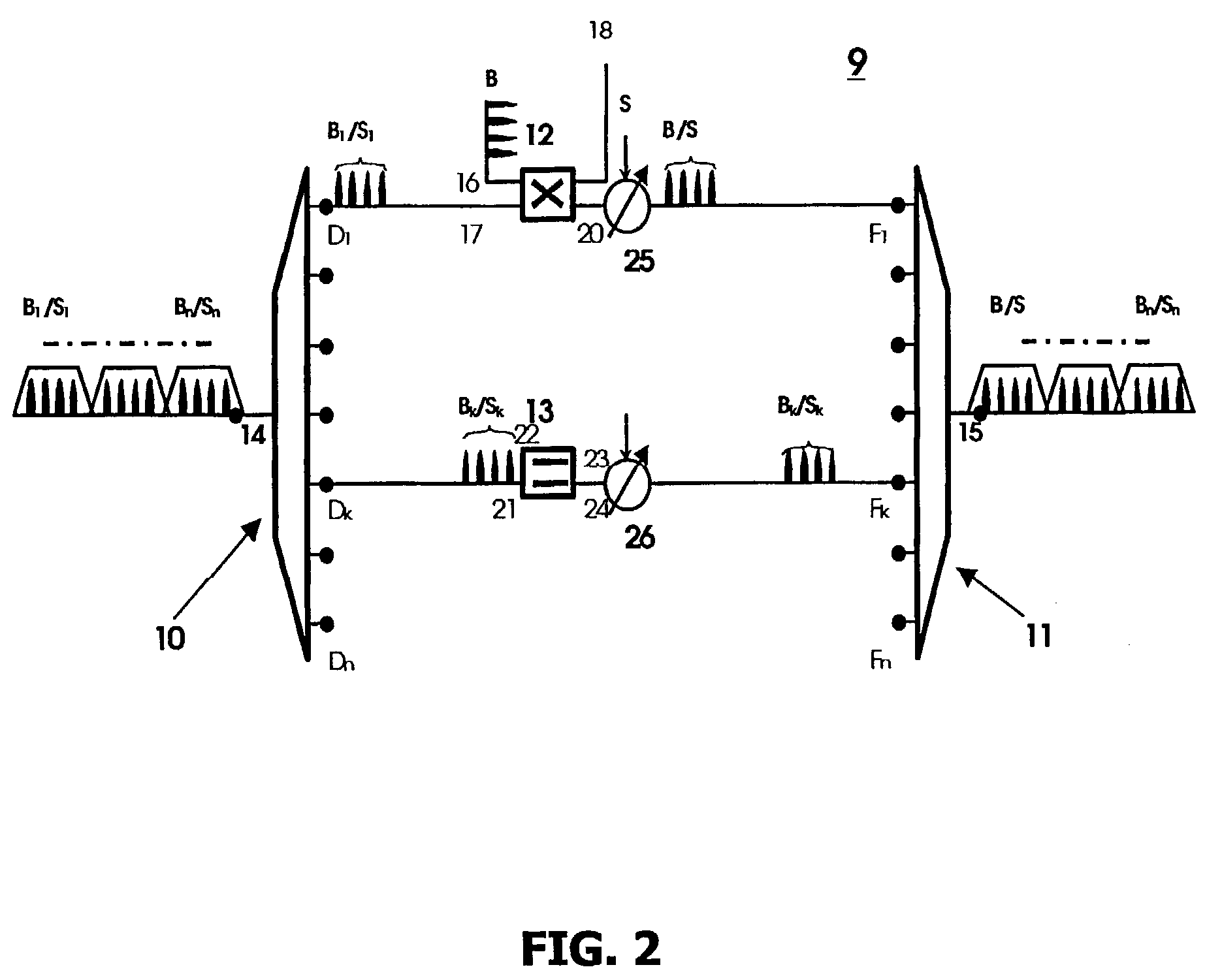
[0035]Items common to both figures are identified by the same reference symbols in both figures.

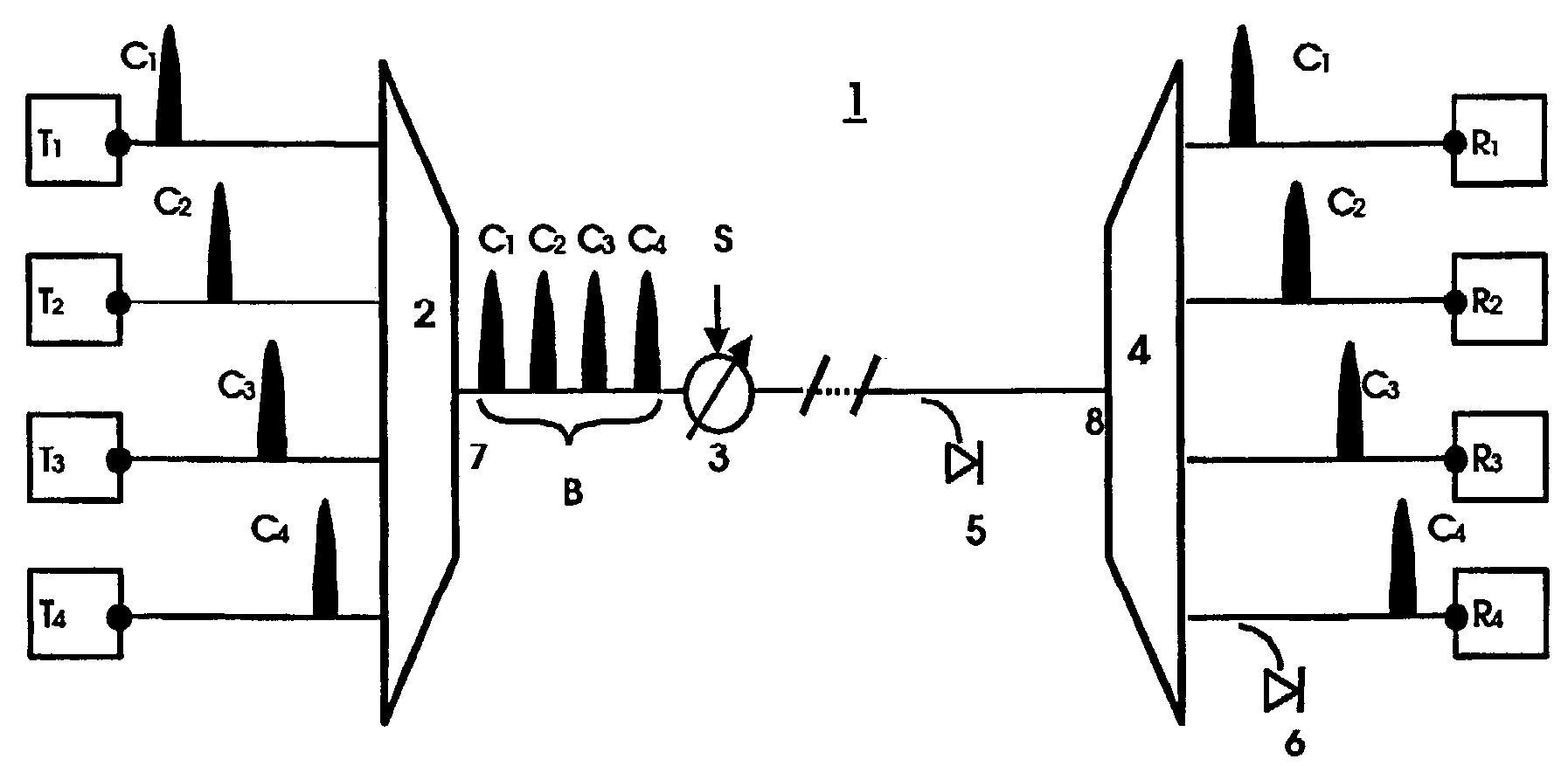
[0036]FIG. 1 shows an example of a system 1 for implementing a method of inserting a monitoring signal, in accordance with the invention.

[0037]Broadly speaking, the system 1 comprises a multiplexer 2 and a variable optical attenuator 3 on the transmitter side and photodiodes 5 and 6 and a demultiplexer 4 on the receiver side.

[0038]In the example shown, the multiplexer 2 has four input ports (Ti)1≦i≦4 and one input port 7 and the demultiplexer 4 has one input port 8 and four output ports (Ri)1≦i≦4.

[0039]At respective input ports (Ti)1≦i≦4 the multiplexer 2 receives a plurality of input optical signals. Each input signal takes the form of modulation of a carrier wave having a predefined wavelength defining a transmission channel (Ci)1≦i≦4. The modulation is often amplitude modulation, but can also be optical phase modulation or optical frequency modulation. The modulation is synchronized by...


PUM


Abstract

The present invention relates to a method of monitoring the transmission of optical signals including a step of inserting a monitoring signal (S) more particularly suited to monitoring the quality of service. During the transmission of optical signals each carried by a predefined wavelength defining a transmission channel (Ci), said signals are grouped onto the same fiber in a band (B) of channels. The method then includes a step of simultaneously modulating said signals grouped in the band of channels using the monitoring signal to be transmitted, so that each of the signals constitutes a carrier of the monitoring signal.

Description

[0001]The present invention relates to a method and to a system for monitoring the transmission of optical signals that are more particularly suited to monitoring quality of service.BACKGROUND OF THE INVENTION[0002]In recent years an enormous demand for bandwidth has been generated by the deployment of modern forms of telecommunication, in particular the Internet and its main application, the World Wide Web, as well as private networks of diverse enterprises and organizations, without forgetting wireless communications, in particular mobile telephones, which in practice requires powerful terrestrial infrastructures if the expectations of customers are not to be disappointed. To face up to this demand, those responsible for providing the networks necessary for the deployment of these new forms of communication have rapidly had to convert to transporting signals carrying information in optical form, in the first place to benefit from the low cost of optical fibers, and in the second p...

Claims


Application Information

Patent Timeline
Patent Type & Authority Patents(United States)
IPC IPC(8): H04B10/08H04J14/00H04J14/02H04B10/077H04B10/079
CPCH04B10/077H04B10/07955H04J14/0212H04J14/0246H04J14/0227H04J14/0213H04B2210/258H04J14/0279H04J14/0298
Inventor BISSON, ARNAUDFAURE, JEAN-PAULNOIRIE, LUDOVIC
Owner RPX CORP
Why Eureka
Try Eureka