Displacement instrument for determining the modulus of a material

a displacement instrument and material technology, applied in the direction of instruments, mechanical measuring arrangements, apparatus for force/torque/work measurement, etc., can solve the problems of excessive over-design, lack of modulus consistency of each pier within the entire construction site, and lack of modulus consistency of each layer of aggregate within the pier

Inactive Publication Date: 2007-11-20
CONNER CHARLES C
View PDF16 Cites 4 Cited by
  • Summary
  • Abstract
  • Description
  • Claims
  • Application Information

AI Technical Summary

Benefits of technology

[0017]When loose aggregate is confined in a container with a controlled applied force, the modulus (density) may be determined by measuring the displacement of the tool used to apply the force. In the case of a foundation the axis of the applied force delivered by an appropriate tool to the aggregate is vertical therefore the measurement of the vertical displacement of the tool is directly related to the modulus of the aggregate. This procedure maintains a uniform modulus throughout the pier and throughout all of the piers of the project. This method will eliminate the approximation procedures of the present construction process.

Problems solved by technology

One weakness in the aggregate pier method is the lack of modulus consistency in each layer of aggregate within the pier and the modulus consistency of each pier within the entire construction site.
This inconsistency in the pier modulus results in excessive over design with all of the undesirable effects that over design creates.

Method used


Image

  • Displacement instrument for determining the modulus of a material
  • Displacement instrument for determining the modulus of a material
  • Displacement instrument for determining the modulus of a material

Examples


Embodiment Construction

[0026]The novel displacement instrument will now be described by referring to FIGS. 1-8 of the drawings. The displacement instrument is generally designated numeral 10.

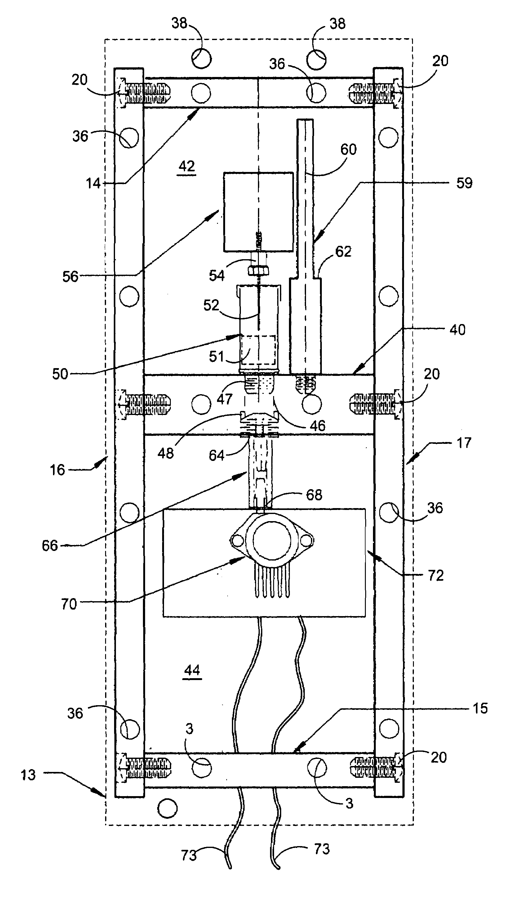
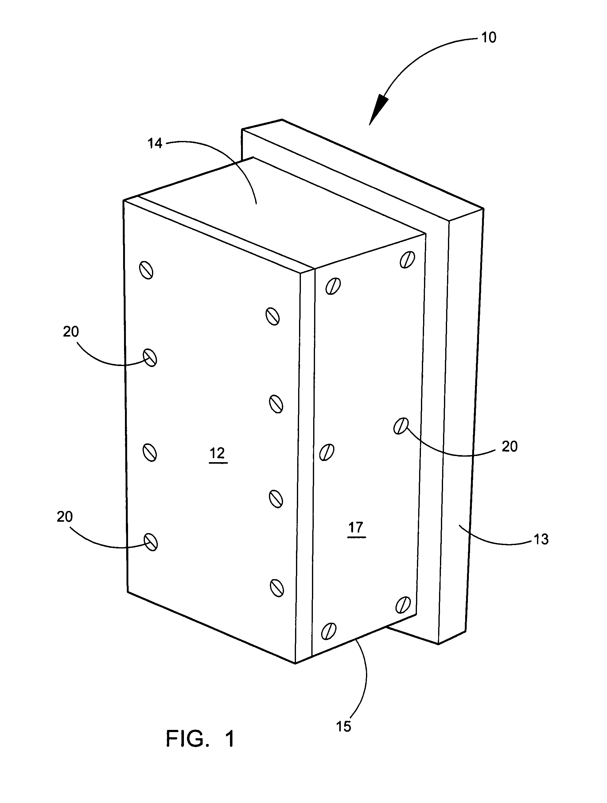
[0027]FIG. 1 shows the displacement instrument 10 having a housing or casing formed from a front cover plate wall 12, a rear plate wall 13, a top plate wall 14, a bottom plate wall 15, a left side plate wall 16 and a right side plate 17. The respective plates have a thickness in the order of ⅜ inch although they could be either thicker or thinner. The plates would normally be made from aluminum or a steel alloy, although other materials could be used. The respective plate members are connected to each other by bolts 20. The housing casing illustrated has an approximate width of 4 inches, an approximate depth of 4 inches and a height of approximately 10 inches. These dimensions are not critical and larger or smaller dimensions might be used in different applications.

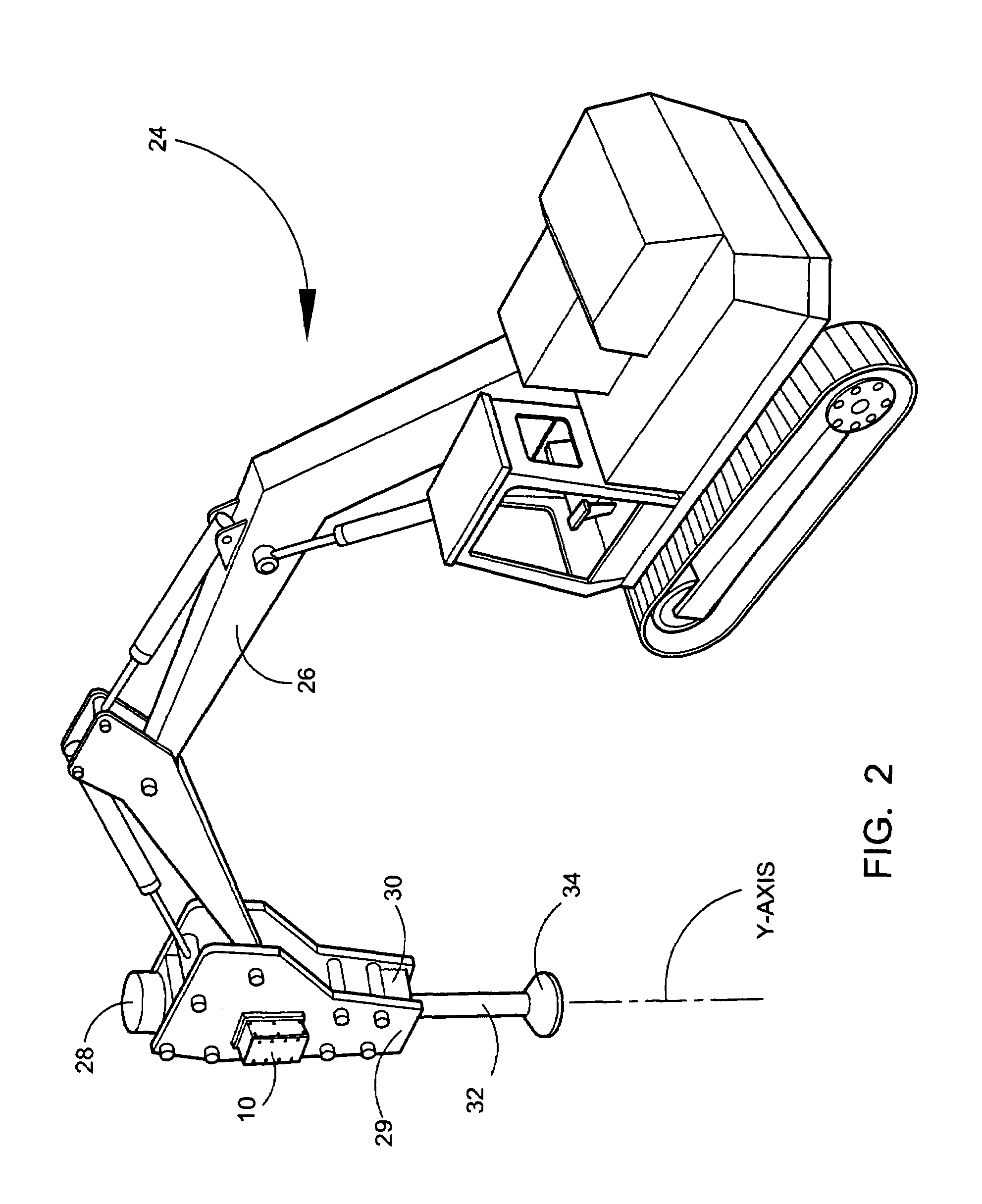
[0028]A crane 24 is illustrated in FIG. 2 having an a...


PUM

PropertyMeasurementUnit
heightaaaaaaaaaa
depthaaaaaaaaaa
widthaaaaaaaaaa

Abstract

A novel displacement instrument that can be used to measure the density or modulus of an aggregate pier upon which a multistory building or parking garage can be built. The aggregate piers are often 35 feet or deeper. These aggravate piers are constructed by adding lifts of approximately 12 to 18 inches of aggregate at a time and tamping it into the pier forming hole. Each lift of aggregate is being tamped or struck by a force of approximately 15,000 psi or greater. The displacement instrument allows aggregate piers to be constructed having a density or modulus that is consistent from the bottom of the hole to the top of the hole. The displacement instrument would be mounted on the side plate of a hydraulic breaker that is mounted on the end of a boom of a crane. The displacement instrument need not be permanently installed on the side of the hydraulic breaker and it is freely removed and installed on another crane.

Description

BACKGROUND OF THE INVENTION[0001]The invention relates to a measuring instrument and more specifically to an instrument for measuring the density or modulus of material that has been subjected to compression forces.[0002]All earth materials possess specific discrete strength and compression characteristics that must be defined in order to design structures to be supported on those materials. These various characteristics are referred to as the soil's “Engineering Properties.” One of these properties is the soil “modulus,” which relates deformation of the soil to an applied load that causes the deformation. Modulus is a very significant engineering property for designing floor slabs on-grade and footings, and for estimating settlements.[0003]Engineering properties of soils can be determined by means of special field and / or laboratory tests. Laboratory tests are often of questionable value due to the inability of the engineer to obtain a truly “undisturbed” sample of the soil for the ...

Claims


Application Information

Patent Timeline
Patent Type & Authority Patents(United States)
IPC IPC(8): G01L7/16G01B5/30G01D11/24
CPCE02D1/02G01N3/48E02D1/022G01N2203/0044
Inventor CONNER, CHARLES C.
Owner CONNER CHARLES C
Why Eureka
Try Eureka