Method and device for monitoring a flexible pipe

a flexible pipe and monitoring device technology, applied in the direction of fluid loss/gain rate measurement, fluid tightness measurement, instruments, etc., can solve the problems of pipe twisting and increase the gas flow in the annulus, and achieve the effect of increasing the detection certainty

Active Publication Date: 2007-11-20
TECH FRANCE SA
View PDF18 Cites 27 Cited by
  • Summary
  • Abstract
  • Description
  • Claims
  • Application Information

AI Technical Summary

Benefits of technology

[0024]It is possible, and even recommended, to combine the two mo

Problems solved by technology

This is because breakage of the armor wires in the end-fitting results in an imbalance in the forces and tensions in the superposed plies, resulting in a twist in the pipe.
The fracture of the armor wires in the end-fitt

Method used


Image

  • Method and device for monitoring a flexible pipe
  • Method and device for monitoring a flexible pipe

Examples


Embodiment Construction

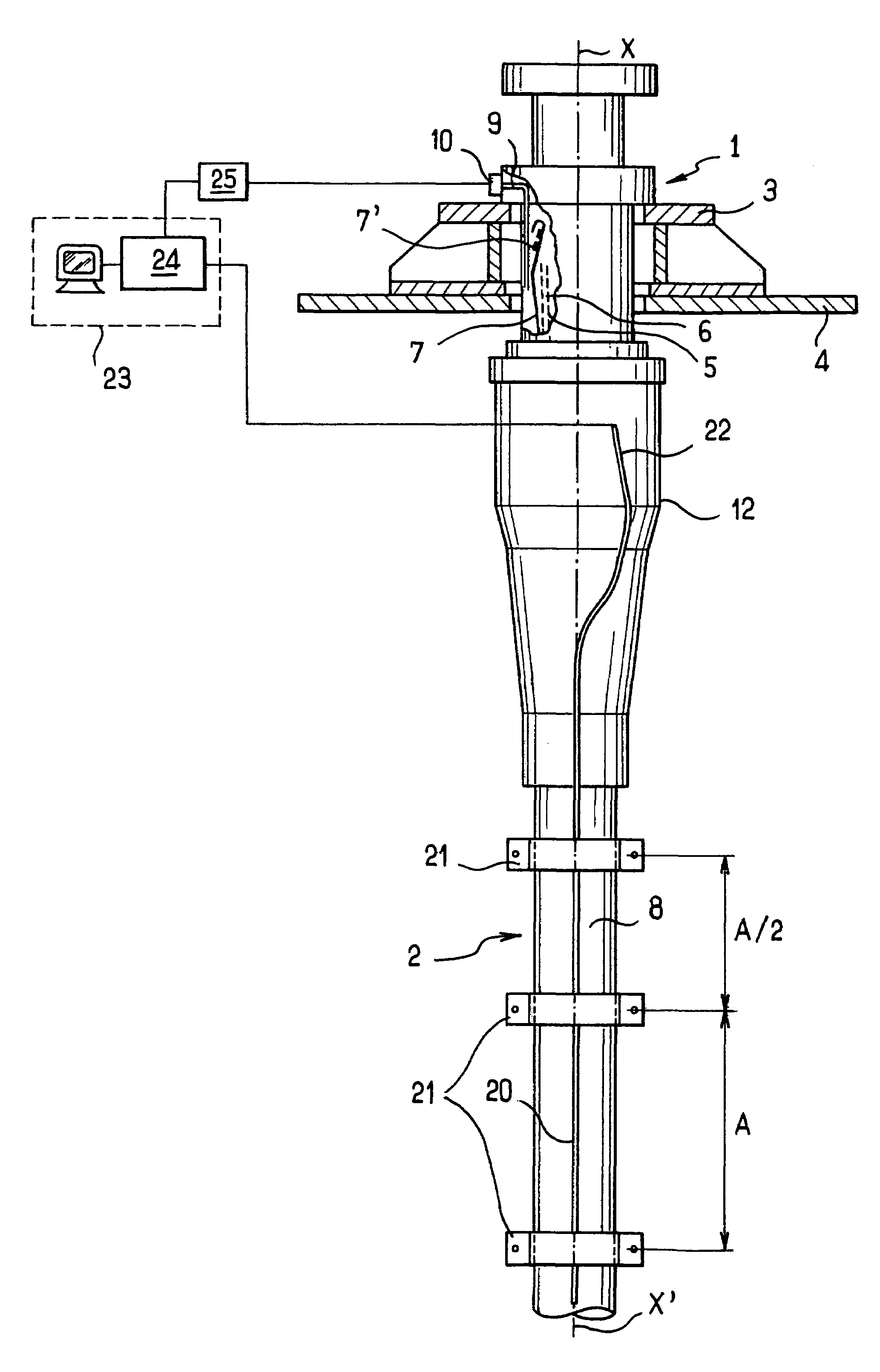
[0029]The FIGURE shows highly schematically an end-fitting 1 which is symmetric about its longitudinal axis XX′ coincident with the central axis of the pipe 2. The end-fitting, partially covered with a stiffener 12, includes a connection flange 3 for fastening to a platform 4. The pipe 2 comprises, as is known, a carcass 5 and its pressure sheath 6, tensile armor plies 7 and an outer sheath 8. These various constituent elements are fastened and crimped to the inside of the end-fitting 1 by various means known per se, especially those known from document WO 02 / 39003 or document U.S. Pat. No. 6,039,083. For example, the armor plies may be held in place by collars 7′ and embedded in a resin. Moreover, the gases appearing in the annulus of the pipe 2 are connected in a line 9 that communicates with the outside via a staged valve 10 or gas drainage valve (only one of the three valves normally present has been shown). A staged differential valve is known, for example from document FR 2 77...


PUM


Abstract

A device for monitoring the integrity of a flexible pipe used for transporting a pressurized fluid in a terminal end-fitting. The pipe includes an internal pressure sheath, plies of tensile armor wires and an outer sheath fastened to the end-fitting. A device monitors the change in a phenomenon associated with a failure of the armor plies as a result of a fracture of several tensile armor wires inside the end-fitting. The device detects an increase in the twist in the pipe near the end-fitting, which twist is a phenomenon of a fracture of tensile armor wires inside the end-fitting.

Description

CROSS REFERENCE TO RELATED APPLICATION[0001]The present application is a 35 U.S.C. §§ 371 national phase conversion of PCT / FR2003 / 002694 filed 11 Sep. 2003, which claims priority of French Application No. 02 / 11556 filed 18 Sep. 2002. The PCT International Application was published in the French language.BACKGROUND OF THE INVENTION[0002]The present invention relates to a method of monitoring a flexible pipe for transporting, over long distances, a fluid that is under pressure and possibly at a high temperature, such as a gas, oil, water or other fluids. The invention relates more particularly to the monitoring and warning of problems associated with a fracture of the armor wires of the flexible pipe in the vicinity of or inside the terminal end-fitting, where they are anchored, especially in a terminal end-fitting for a rising flexible pipe, called a “riser”, intended for offshore oil production. The present invention also relates to a device associated with the monitoring method.[00...

Claims


Application Information

Patent Timeline
IPC IPC(8): G01N3/26F17D5/06G01M3/04G01M3/28
CPCE21B47/0001E21B47/0006G01M3/283G01M3/047F17D5/06E21B47/001E21B47/007
Inventor DE AQUINO, ROBERTO JOURDAN
Owner TECH FRANCE SA
Why Eureka
Try Eureka