Supercharge Your Innovation With Domain-Expert AI Agents!

Mechanical system for power change between the input and output thereof

a mechanical system and power supply technology, applied in the direction of toothed gearings, gearing elements, gearing rings, etc., can solve the problems of large, complex and expensive power loss in transmission and distribution systems, and generators are not 100% efficien

Inactive Publication Date: 2007-11-20
QUINN IND LLC
View PDF7 Cites 31 Cited by
  • Summary
  • Abstract
  • Description
  • Claims
  • Application Information

AI Technical Summary

Benefits of technology

"The present invention is a device that includes two power disc elements that rotate about a central axis. The first power disc element has a first peripheral gear and a first system gear that is offset from the central axis. The second power disc element has a plurality of outer drive gear members and a central gear that is fixed relative to the central axis. The first system gear is connected to the outer drive gears on the first power disc element, and the second system gear is connected to the peripheral gear portion on the second power disc element. The device allows for rotation of the first and second power disc members when the first system gear is turned by a motor. The invention also allows for a power change between the first and second system shafts."

Problems solved by technology

Electric power produced by such plants is then supplied to individual users, through large, complex and expensive transmission and distribution systems.
Power is lost in the transmission and distribution system.
These generators are also not 100% efficient.
Electric motors are also less than 100% efficient, as are systems using electric power directly, such as lighting systems.
Some energy is lost in carrying out specific work, i.e. turning a shaft or lighting a filament in a bulb, for instance.
One example is for powering irrigation systems in, for instance, third world countries, where the cost of energy to run such systems adds significantly to the cost of food production.

Method used


Image

  • Mechanical system for power change between the input and output thereof
  • Mechanical system for power change between the input and output thereof
  • Mechanical system for power change between the input and output thereof

Examples


Embodiment Construction

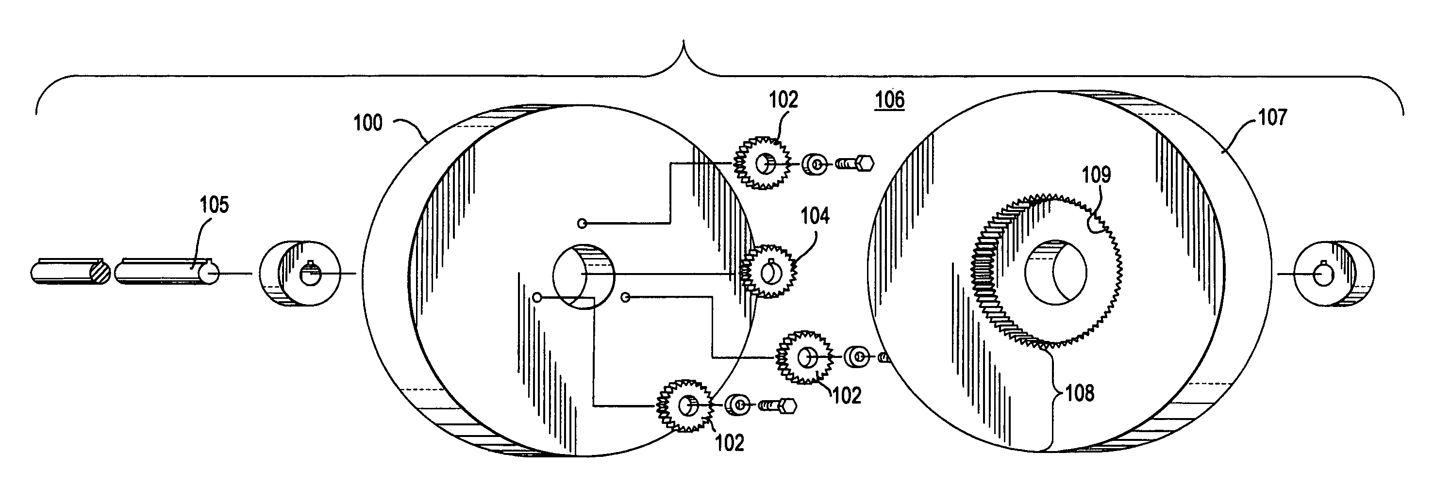
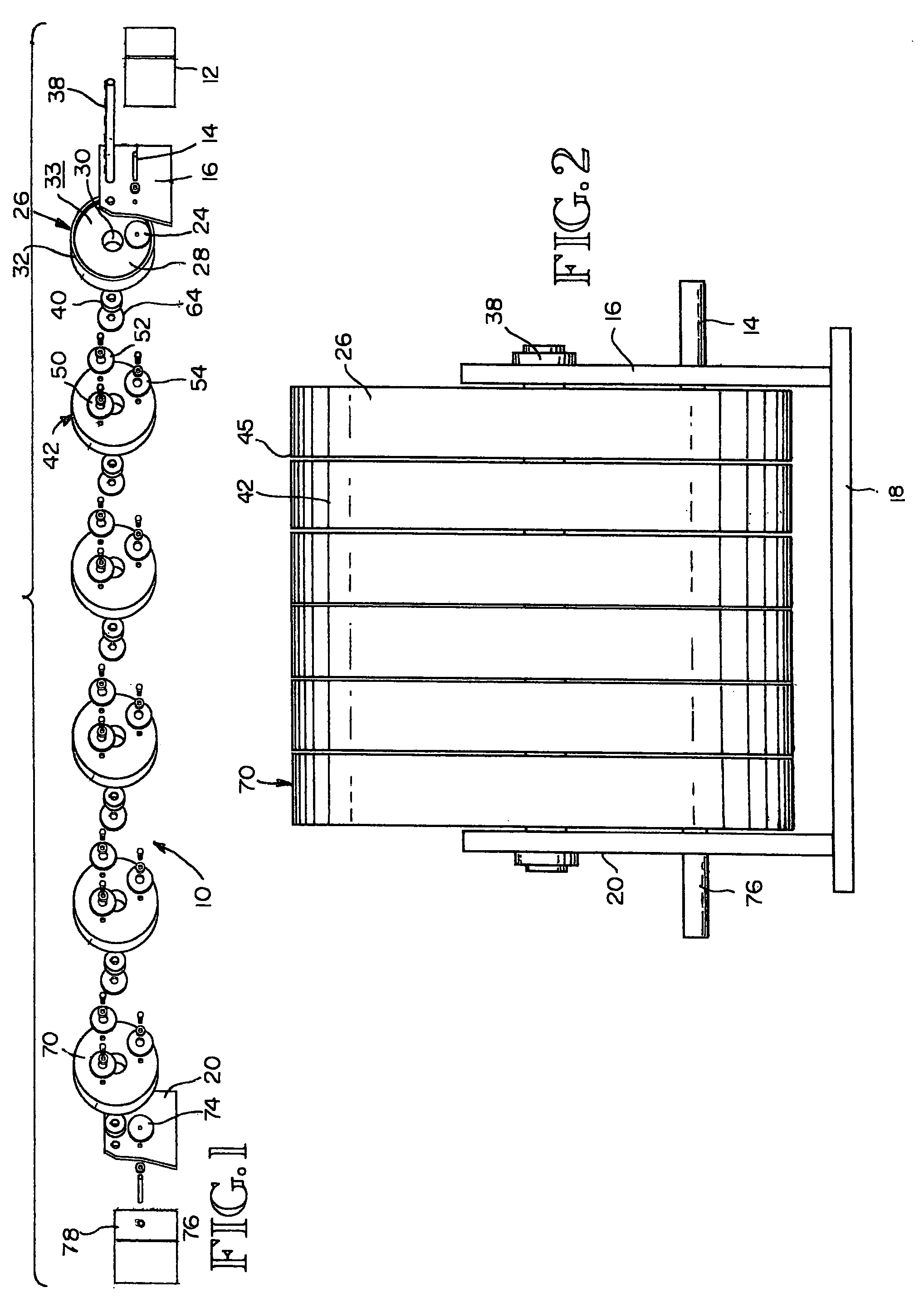
[0015]The system of the present invention, shown generally in one embodiment at 10 in FIG. 1, produces an efficient power change between the input and output ends of the system. The system, generally shown at 10, is driven by a conventional electric motor 12 at one end of the system 10 in FIG. 1. Other power sources could also be used, including a gas or diesel engine system or other power systems. In the embodiment shown, electric motor 12 is relatively small, i.e. a two horsepower, single-phase motor, operating at 110 volts. However, it should be understood that the input motor could be significantly larger and / or could be a three-phase motor operating at 220 volts. The characteristics of the drive motor are not critical to the present invention.

[0016]Electric motor 12 includes a conventional output shaft 14, also referred to herein as a system input power shaft, which extends through a first fixed support bracket 16. Support bracket 16 supports the present power system at one end...


PUM


Abstract

The system includes at least two power disc elements, each mounted for rotation on a central shaft which is typically fixed. The first power disc element includes a first peripheral gear portion by which the first power disc element may be turned by an input assembly. The first power disc element has a second gear portion which may have a substantially smaller diameter than the outside diameter thereof. A second power disc portion has a plurality of outer drive gears mounted for rotation to mate with the second peripheral gear portion on the first power disc element. A central gear, which may be substantially larger than the outer drive gears, is positioned to mate with the outer drive gear in the the second power disc element. The second power disc element drives an output assembly.

Description

TECHNICAL FIELD [0001]This invention relates generally to a system for supplying power at an output in response to an input source thereof, and more particularly concerns such a system which produces a power change between the input and outputs thereof.BACKGROUND OF THE INVENTION [0002]The generation of power, and correspondingly, machines which use power to produce work, such as by the turning of a shaft by electric power, are quite important to modern industry and society. Electric power is used to run a large number of machines which vary substantially in output capability, depending upon the task, from less than one horsepower to several thousand horsepower and even greater, to accomplish specific tasks. Electric power is also used to power electric lights and many electric appliances.[0003]The sources of electric power also vary widely, including large electric power generating plants using, for instance, hydroelectric capability, fossil and / or nuclear fuels, among others. Elec...

Claims


Application Information

Patent Timeline
Patent Type & Authority Patents(United States)
IPC IPC(8): F16H33/00F16H35/00F16H37/00F16H37/06F16H57/08
CPCF16H1/46F16H57/033F16H1/10Y10T74/19Y10S475/903Y10T74/19642F16H57/02
Inventor QUINN, TODD C
Owner QUINN IND LLC
Features
  • R&D
  • Intellectual Property
  • Life Sciences
  • Materials
  • Tech Scout
  • Unparalleled Data Quality
  • Higher Quality Content
  • 60% Fewer Hallucinations
Learn More