Device for dispensing a heated liquid having a flexible hydraulic seal

a hydraulic seal and device technology, applied in liquid transferring devices, instruments, volume meters, etc., can solve the problems of critical surface machining on the surface of the valve element, unfavorable leakage, and reduce the lifespan of the seal

Active Publication Date: 2007-11-20
NORDSON CORP
View PDF27 Cites 18 Cited by
  • Summary
  • Abstract
  • Description
  • Claims
  • Application Information

AI Technical Summary

Benefits of technology

[0006]The present invention provides for a device for dispensing a heated liquid having a flexible hydraulic seal. To this end, the device includes a heated dispenser body having a liquid inlet in fluid communication with a heated manifold to receive a heated liquid, a liquid passage in communication with the liquid inlet, and a liquid outlet in communication with the liquid passage. The dispenser body further includes a valve element having an outer surface with a circumferential groove therearound and is adapted to selectively allow and prevent flow of the heated liquid through the outlet from the liquid passage.
[0008]A flexible seal is situated within the cavity separating the liquid passage containing the heated liquid and an upper area of the dispenser body. The seal is a standard O-ring type seal composed of an elastomeric material, such as a fluorelastomer, or may be a spring-energized cup seal. A first portion of the seal is configured to form a fluid-tight seal within the recessed portion and a second portion is configured to form a fluid-tight seal about the valve element during reciprocation thereof relative to the recessed portion. The seal is situated so that the second portion flexes about a central axis of the valve element during reciprocation while the first portion remains relatively stationary within the recessed portion. This seal arrangement prevents liquid from leaking out of the liquid passage past the flexible seal into the upper area and further helps extend the lifespan of the seal.

Problems solved by technology

This seal arrangement, commonly referred to as a sliding-fit condition, can reduce the lifespan of the seal due to the reciprocating axial movement along the inner surface of the dispenser body.
Also, costly, critical-surface machining on the surface of the valve element is required to provide the tight fit for the seal.
Furthermore, the sliding-fit condition has a tendency to permit unfavorable leakage between the seal interface and the valve element.
This leakage can reduce the performance of the dispensing device, for example, by decreasing the lifespan of the actuating element.

Method used


Image

  • Device for dispensing a heated liquid having a flexible hydraulic seal
  • Device for dispensing a heated liquid having a flexible hydraulic seal
  • Device for dispensing a heated liquid having a flexible hydraulic seal

Examples


Embodiment Construction

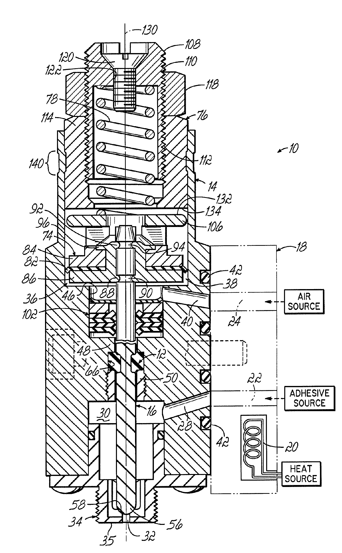
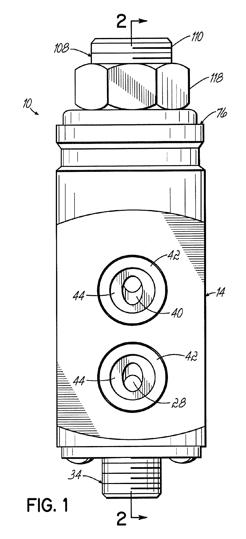
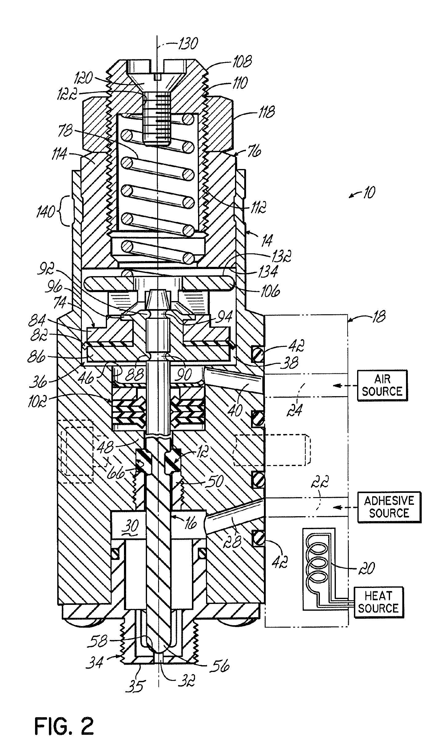
[0018]As shown in FIGS. 1 and 2, a device 10 for dispensing a heated liquid (not shown), such as a hot melt adhesive, having a flexible hydraulic seal 12 generally includes a dispenser body 14 having a valve element 16 adapted to be pneumatically driven for dispensing discrete amounts of the heated liquid. One alternative to the device 10 of FIG. 1 could be an electrically actuated dispenser device (not shown) instead of the pneumatically actuated dispenser device 10. A suitable pneumatically driven device 10 that may be modified to incorporate the flexible hydraulic seal 12 of the present invention is disclosed in U.S. Pat. No. 6,056,155 to Byerly et al., which is hereby fully incorporated herein by reference.

[0019]The dispenser body 14 is adapted to be heated and is constructed from a heat transferable, non-interactive metal, such as aluminum, brass, stainless steel, or the like. The dispenser body 14 further is coupled by means commonly known in the art, such as bolts or screws, ...


PUM


Abstract

A device for dispensing a heated liquid, such as a hot melt adhesive, which includes a heated dispenser body having a liquid passage in communication with a liquid inlet and a liquid outlet. The dispenser body further includes a valve element having a circumferential groove therearound cooperating with a recessed portion of the dispenser body to define a cavity about the valve element. A flexible seal is situated within the cavity between the liquid passage containing the heated liquid and an upper area of the dispenser body. A first portion of the seal is configured to form a fluid tight seal within the recessed portion and a second portion is configured to form a fluid tight seal about the valve element during reciprocation thereof relative to the recessed portion, thereby preventing liquid from leaking out of the liquid passage past the flexible seal and into the upper area.

Description

FIELD OF THE INVENTION[0001]The present invention pertains generally to devices for dispensing a heated liquid and, more particularly, to a device for dispensing a heated liquid having a flexible hydraulic seal.BACKGROUND OF THE INVENTION[0002]A typical dispensing device for supplying a heated liquid, such as a hot melt adhesive, generally includes a heated dispenser body constructed from a heat transferable metal, such as aluminum, brass, or stainless steel, and typically is coupled to a manifold, or other heater block, adapted to heat a liquid. The dispenser body includes a liquid inlet in fluid communication with the manifold to receive the heated liquid, and further includes a valve element that opens and closes a liquid outlet in communication with the inlet for dispensing discrete amounts of the heated liquid.[0003]The valve element is usually operated by pressurized air to dispense the heated liquid. As such, an air passage or chamber typically is located in an upper area of ...

Claims


Application Information

Patent Timeline
Patent Type & Authority Patents(United States)
IPC IPC(8): B67D3/00
CPCF16K49/002F16J15/064B05C5/0225B05C5/001
Inventor BYERLY, DAVID J
Owner NORDSON CORP
Why Eureka
Try Eureka