Device for examining the precision of a circular path which is to be executed by a working spindle

a technology of working spindle and circular path, which is applied in the direction of programmed manipulators, milling equipments, measuring/indication equipments, etc., can solve the problems of only examining fixed diameters and defined diameters of circular cylindrical surfaces, and achieves easy adjustment, easy exchange or replacement, and easy determination

Active Publication Date: 2007-11-20
DREIER TECH GMBH
View PDF13 Cites 40 Cited by
  • Summary
  • Abstract
  • Description
  • Claims
  • Application Information

AI Technical Summary

Benefits of technology

[0011]Threaded adjusting nuts can be provided as adjusting means of the measuring value sensor which can be urged against opposite sides of the clamping device and are guided on an outer thread of its measuring arm. These adjusting means provide exact diameter adjustment of the circular cylindrical surfaces. In a further improvement, the measuring arm and the clamping device are designed such that the measuring arm length which is effective for diameter examination can be easily determined via indices.
[0012]In a further preferred embodiment of the invention, the measuring arm of the measuring value sensor can be replaced by others having a different length. The device can thereby be adjusted quickly and easily to different measuring tasks or measuring distances.
[0013]In one construction variant, the measuring arm can be extended by partial arm pieces that can be axially joined. This is advantageous in that measuring arms of different lengths are not required and in case of damage, the measuring arm can be easily exchanged or replaced by others having different measuring paths, e.g. +1, +2, +5, +10 mm.

Problems solved by technology

Extensions are disadvantageous in that they permit examination only of fixed, defined diameters of circular cylindrical surfaces.

Method used


Image

  • Device for examining the precision of a circular path which is to be executed by a working spindle
  • Device for examining the precision of a circular path which is to be executed by a working spindle
  • Device for examining the precision of a circular path which is to be executed by a working spindle

Examples


Embodiment Construction

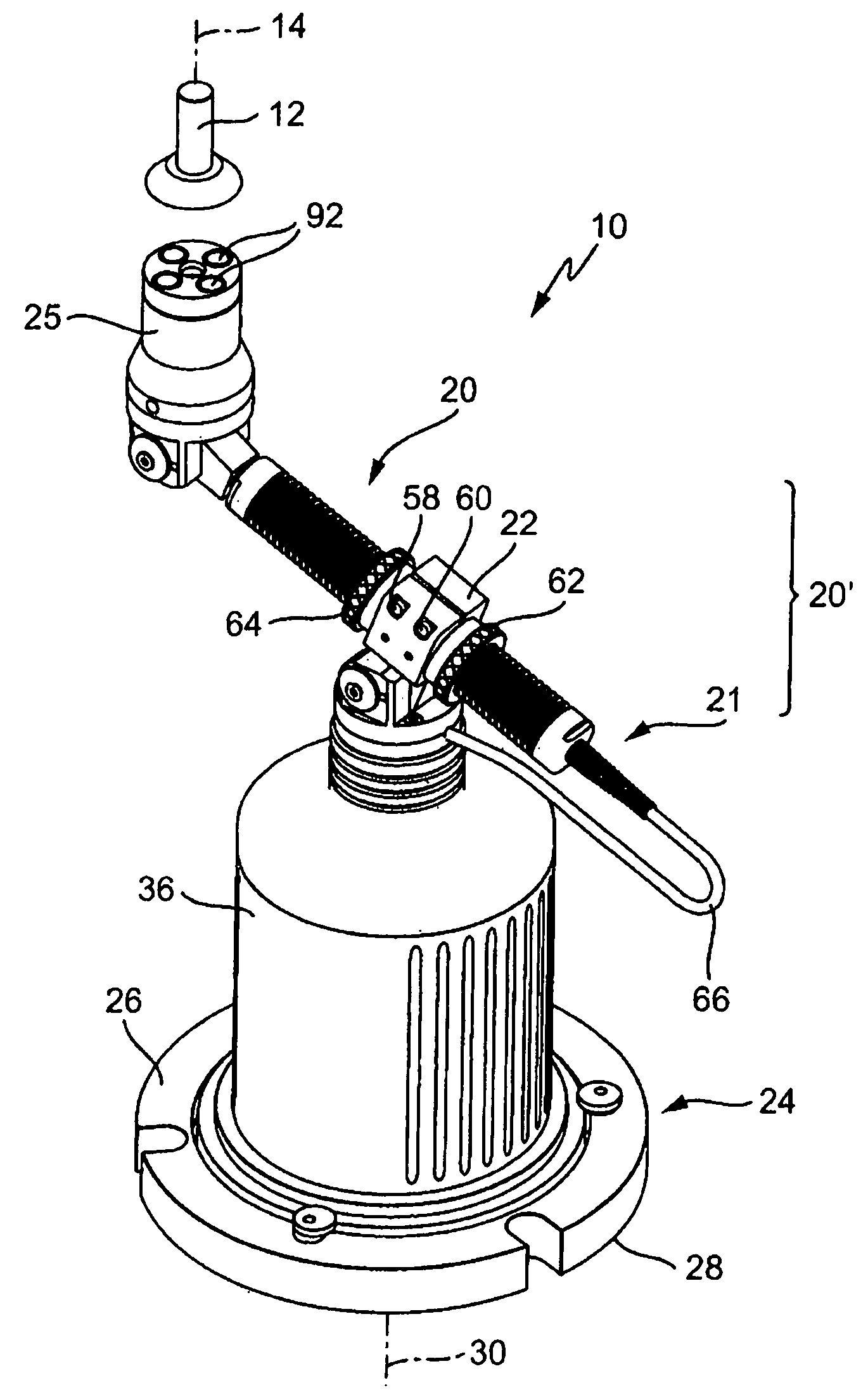
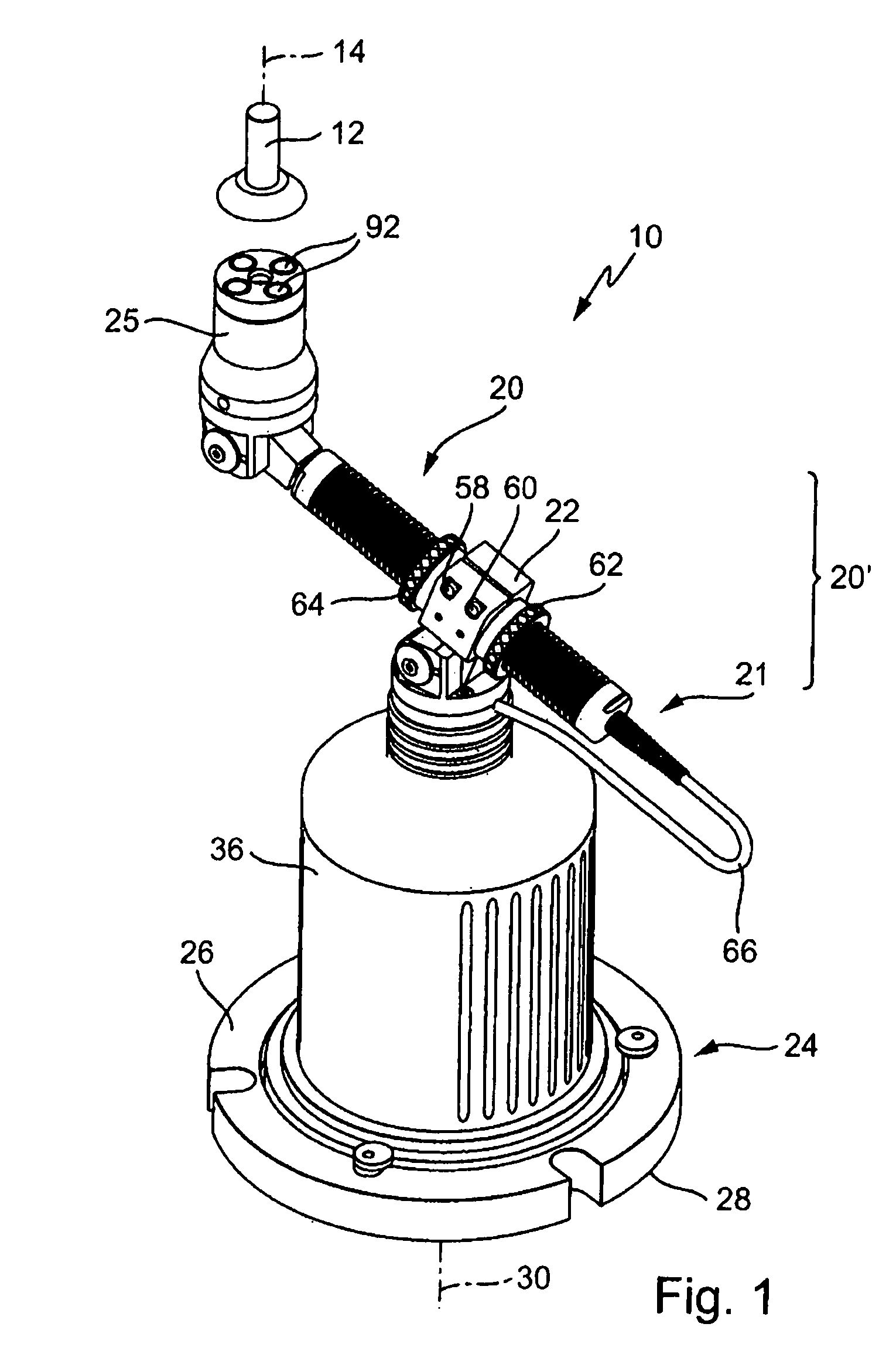
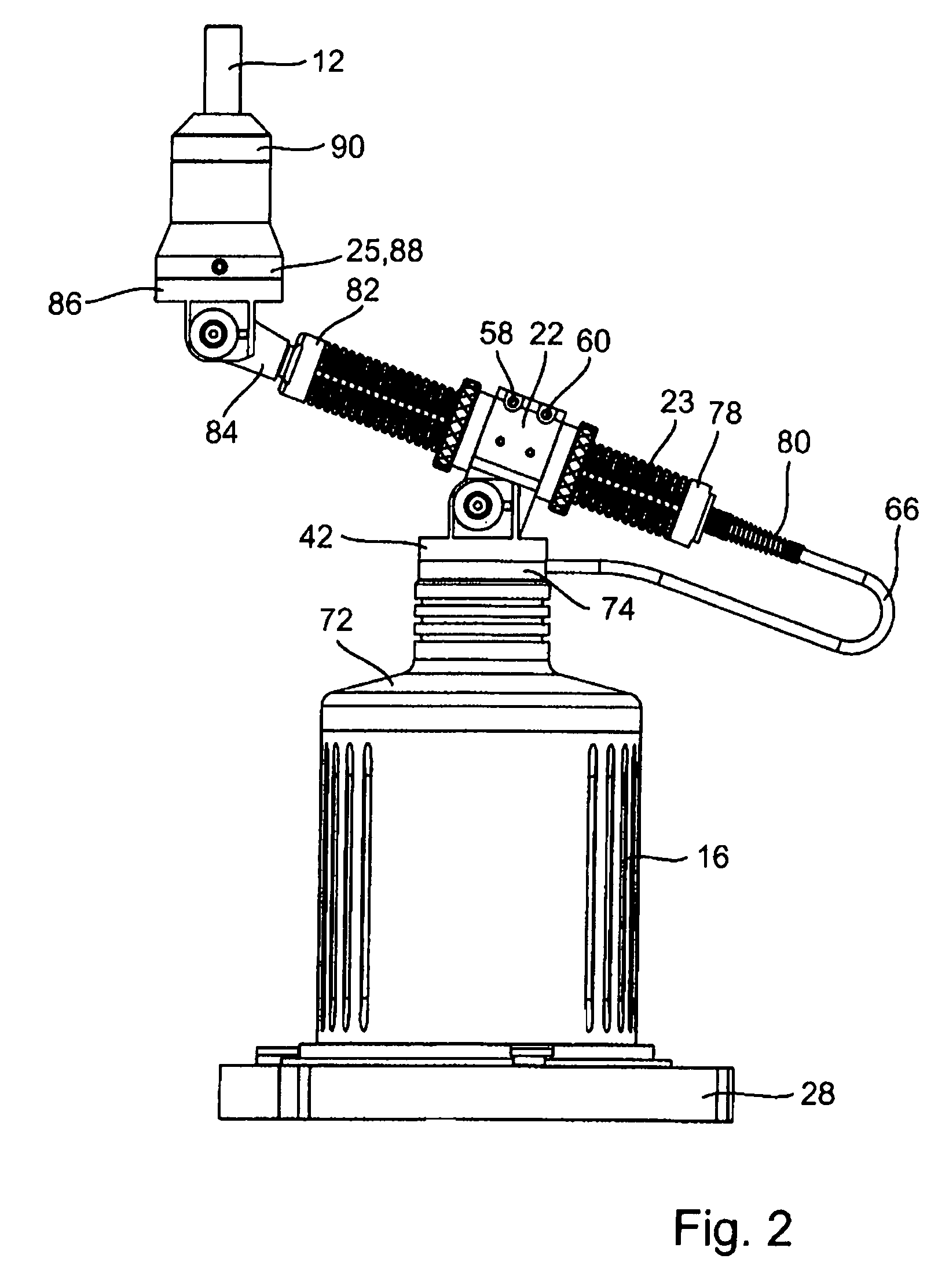
[0023]FIGS. 1 and 2 show an embodiment of a measuring value sensor, designated in total with 21, of an examination device 10, with one device part of the examination device 10 being fixed to a machine table of a machine tool.

[0024]Only one device part is shown and bears a partial piece 20′ of the measuring value sensor 21 forming the measuring arm 20. It is thereby noted that further constructive features of the examination device 10 are given in DE 295 12 250 U1 which discloses all details of the device part, designated in total with 24, which is to be mounted on the table side, except for the measuring arm 20 and its clamping device 22.

[0025]Analogous to this conventional examination device, the device part 24 (called installation unit below) which is to be provided on the table side (see DE 295 12 250 U1) has an associated clamping member 12 forming the further device part, which is to be mounted e.g. in clamping jaws of a working spindle in an NC-controlled machine tool.

[0026]Th...


PUM

PropertyMeasurementUnit
diameteraaaaaaaaaa
lengthsaaaaaaaaaa
lengthaaaaaaaaaa

Abstract

The invention concerns a device for examining the precision of motion of a working spindle of an NC-controlled machine tool along a circular path for producing circular cylindrical surfaces on workpieces, comprising a first device part which can be coaxially mounted to the working spindle, a second device part which can be positioned on a machine table, which receives a workpiece to be processed, coaxially to the axis of a circular cylindrical surface to be produced on the workpiece, an electronic measuring value sensor which extends radially with respect to the axes of working spindle and circular cylindrical surface and is hinged to both device parts, and a shaft encoder which is rotatably disposed in the second device part coaxial relative to the axis of the circular cylindrical surface to be produced to determine the angular position of the measuring value sensor, wherein the measuring value sensor is held on one of the two device parts such that it can be adjusted and fixed transversely to the axes of the working spindle and the circular cylindrical surface.

Description

[0001]This application claims Paris Convention priority of DE 10 2006 009 422.0 filed on Feb. 23, 2006.BACKGROUND OF THE INVENTION[0002]The invention concerns a device for examining the precision of the motion of a working spindle of an NC-controlled machine tool along a circular path for producing circular cylindrical surfaces on workpieces, in accordance with the preamble of claim 1.[0003]There are conventional devices of this type, which form the subject matter of DE 295 12 250 U1.[0004]The device advantageously avoids the need for different reference cylinders to examine the precision of different diameters of circular cylindrical surfaces.[0005]However, the device is only suited to examine one single circular path diameter due to the defined separation of the link points of the measuring sensor extending radially relative to the axes of the working spindle and the circular cylindrical surface to be produced.[0006]It is therefore the underlying purpose of the invention to furthe...

Claims


Application Information

Patent Timeline
Patent Type & Authority Patents(United States)
IPC IPC(8): B23C9/00B23Q17/00B23Q17/22
CPCB25J9/1692G01B21/042Y10T409/306888Y10T409/308624G05B2219/37619
Inventor DREIER, HORST
Owner DREIER TECH GMBH
Why Eureka
Try Eureka