Virtual bracket placement and evaluation

a virtual bracket and placement technology, applied in the field of virtual bracket placement and evaluation, can solve the problems of human error, human inability to determine the ideal location of the bracket, and extremely difficult to manually place the bracket in the estimated ideal location, so as to improve accuracy and consistency.

Inactive Publication Date: 2007-11-20
ORAMETRIX
View PDF12 Cites 45 Cited by
  • Summary
  • Abstract
  • Description
  • Claims
  • Application Information

AI Technical Summary

Benefits of technology

[0018]The invention provides user selectable appliance placement references for enabling the practitioner or the user in placing virtual appliances such as virtual brackets on virtual teeth model of a patient, and in evaluating their effectiveness in realizing the desired goals of the treatment. In a preferred embodiment of the invention, an appliance height reference is provided for facilitating placement of the virtual appliances on a three-dimensional model of a patient's teeth. In a preferred aspect of the invention, the appliance height reference is implemented as a bracket height reference for placing virtual brackets on virtual teeth of a patient. The user selects a value for placing the virtual bracket on the virtual tooth at the desired bracket height from the reference options available on the unified workstation for orthodontic treatment planning, described later on in greater detail, and the unified workstation places and displays the virtual bracket on the virtual tooth at or near the selected height depending upon the tooth surface geometry and texture for suitably accepting the bracket. Alternatively, the user can specify the desired or customized bracket height reference value for placing the virtual bracket on the virtual tooth. The bracket height reference is similar in functionality to the bracket height measured from a bracket height-measuring gauge; but provides much improved accuracy and consistency in the height measurements over the bracket height-measuring gauge. Additionally, meaningful height measurements for crooked or deformed teeth that are very difficult to realize with the bracket height-measuring gauge can easily be made with the bracket height reference of the present invention.
[0023]In its broader aspects, the treatment planning apparatus comprises a workstation having a processing unit and a display, and a memory storing a virtual, complete three-dimensional model representing the dentition of a patient. The virtual three-dimensional model can be obtained from one of several possible sources; including from a scanning of the dentition. The apparatus further includes software executable by the processing unit that accesses the model and displays the model on the display of the workstation. The software further includes navigation tools, e.g., typed commands, icons and / or graphical devices superimposed on the displayed model, that enables a user to manipulate the model on the display and simulate the movement of at least one tooth in the model relative to other teeth in the model in three-dimensional space, and quantify the amount of movement precisely. This simulation can be used, for example, to simulate the bracket placement on virtual teeth of the patient.
[0026]One of the primary tools in the treatment planning apparatus is the selection and customization of a desired or target archform. Again, because the teeth are individual tooth objects, they can be moved independently of each other to define an ideal arch. This development of the target archform could be calculated using interpolation or cubic spline algorithms. Alternatively, it can be customized by the user specifying a type of archform (e.g, Roth), and the tooth are moved onto that archform or some modification of that archform. The archform can be shaped to meet the anatomical constraints of the patient. After the initial archform is designed, the user can again position the teeth on the archform as they deem appropriate on a tooth by tooth basis. The treatment planning software thus enables the movement of the virtual tooth objects onto an archform which may represent, at least in part, a proposed treatment objective for the patient.
[0029]In a preferred embodiment, the method of placing brackets on three-dimensional model of the patient's teeth using bracket placement references includes the step of providing displays on the screen display enabling a user of the workstation to operate the user interface so as to place virtual three-dimensional objects representing orthodontic appliances, e.g., brackets, onto the surface of teeth in the virtual model. A library of the virtual brackets can be stored in memory and a landmarking procedure used to place the brackets on the teeth at the desired location. Anatomical considerations may dictate movement of the brackets from their originally selected position to a new position. Accordingly, the software provides navigational tools enabling a user to change the position of the brackets relative to the teeth.
[0031]The treatment planning software includes features enabling more accurate diagnosis. For one thing, the virtual model of the dentition can be manipulated in three dimensions at will, resulting in complete visual assessment of the model. Measurement tools are also provided by which the orthodontist can determine the distance between any two points on the model. This allows the user to quantify the patient's morphology both at initial and at target stages or states. Thus, treatment progress, proposed changes in appliance design, or tooth movement can be quantified precisely. By measuring the differences and changes in morphology during the care cycle, the orthodontist can quickly and accurately assess patient treatment. Changes in treatment can be made early on. The result is shorter treatment times (and the ability for the orthodontist to service more patients per year).

Problems solved by technology

Unfortunately, in the oral environment, it is impossible, using human sight, to accurately develop a three-dimensional mental image of an orthodontic structure due to the limitations of human site and the physical structure of a human mouth.
Further it is humanly impossible to determine an ideal bracket location to achieve the desired orthodontic structure based on mental images.
It is also extremely difficult to manually place brackets in the estimated ideal location, to control bonding agent thickness, ligation forces, manufacturing tolerances, and biological changes.
Such physical modeling would provide only very limited treatment simulation capability, and could be time consuming and expensive.
However, when the patient's teeth are crooked and hard to measure, e.g., with perverted axial inclination, usefulness of such gauges could be limited; and may not yield the desired accuracy in placing the brackets.
Furthermore, such physical gauges are generally limited in capability in that they are intended for measurements solely from good cusp tips.
Also consistency in measurements is critical, which may be difficult to achieve in manual measurements.
While the '478 patent discloses a method for forming a jig, such jig utilization still keeps the bracket as the focal point of the orthodontic treatment and provides no feedback mechanism regarding actual placement of the bracket.
Further, the '478 patent does not allow for variables associated with tooth movement such as static, dynamic, or psychosocial mechanical and / or biological changes.
Unfortunately, the current innovations to change the practice of orthodontic from an art to a science have only made limited progress.
As such, the tooth will not be repositioned to the desired location.

Method used


Image

  • Virtual bracket placement and evaluation
  • Virtual bracket placement and evaluation
  • Virtual bracket placement and evaluation

Examples


Embodiment Construction

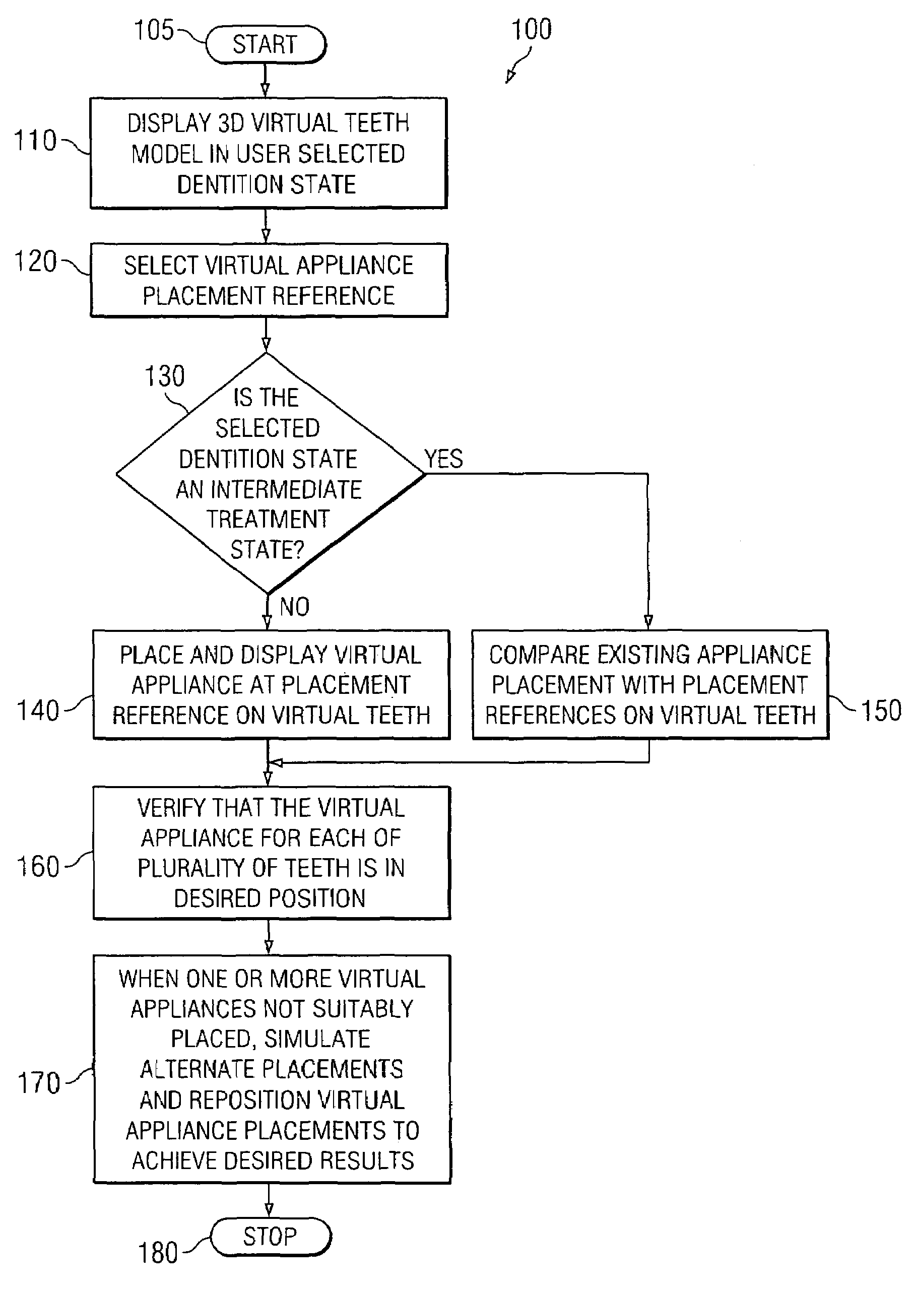
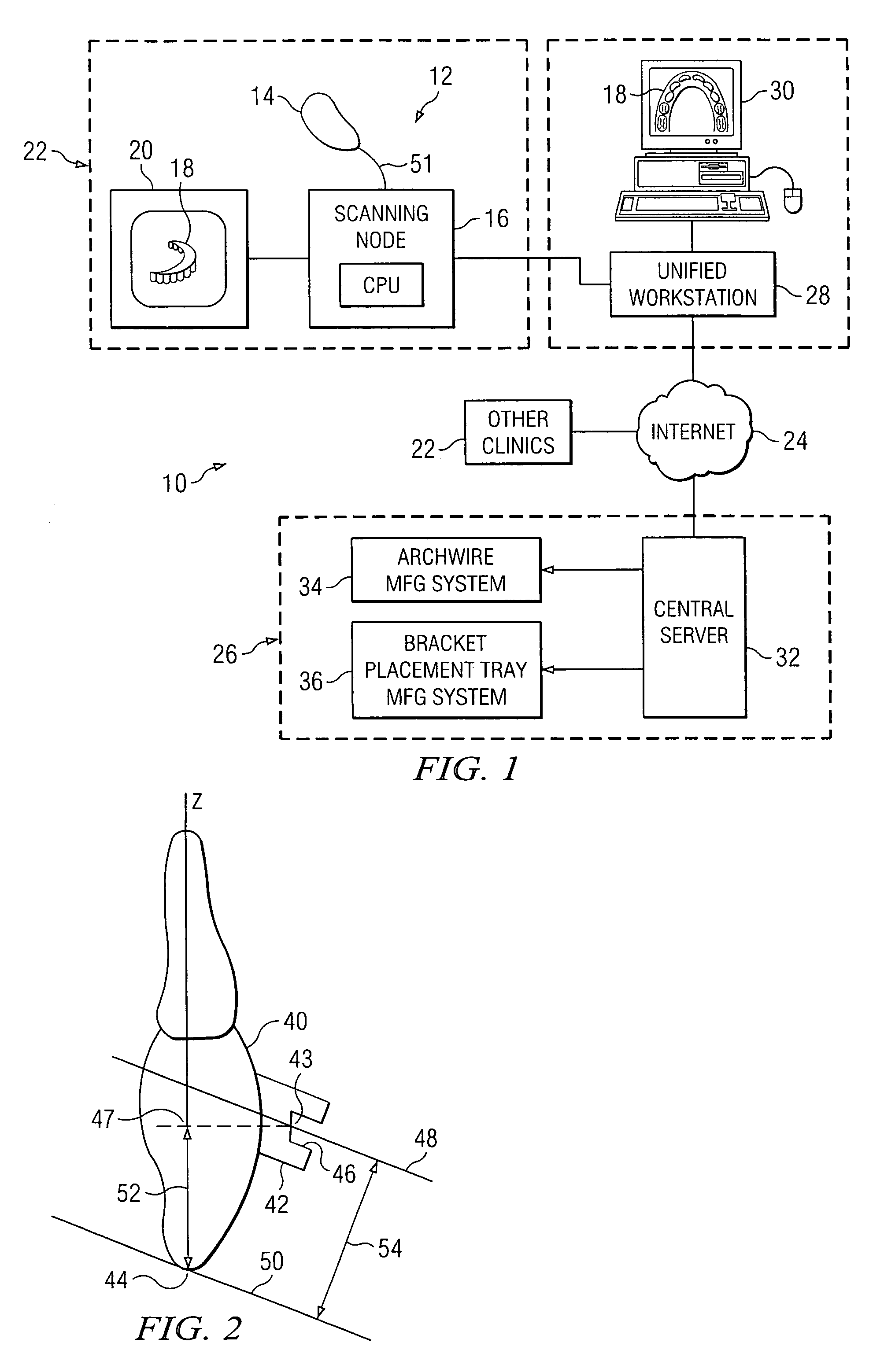
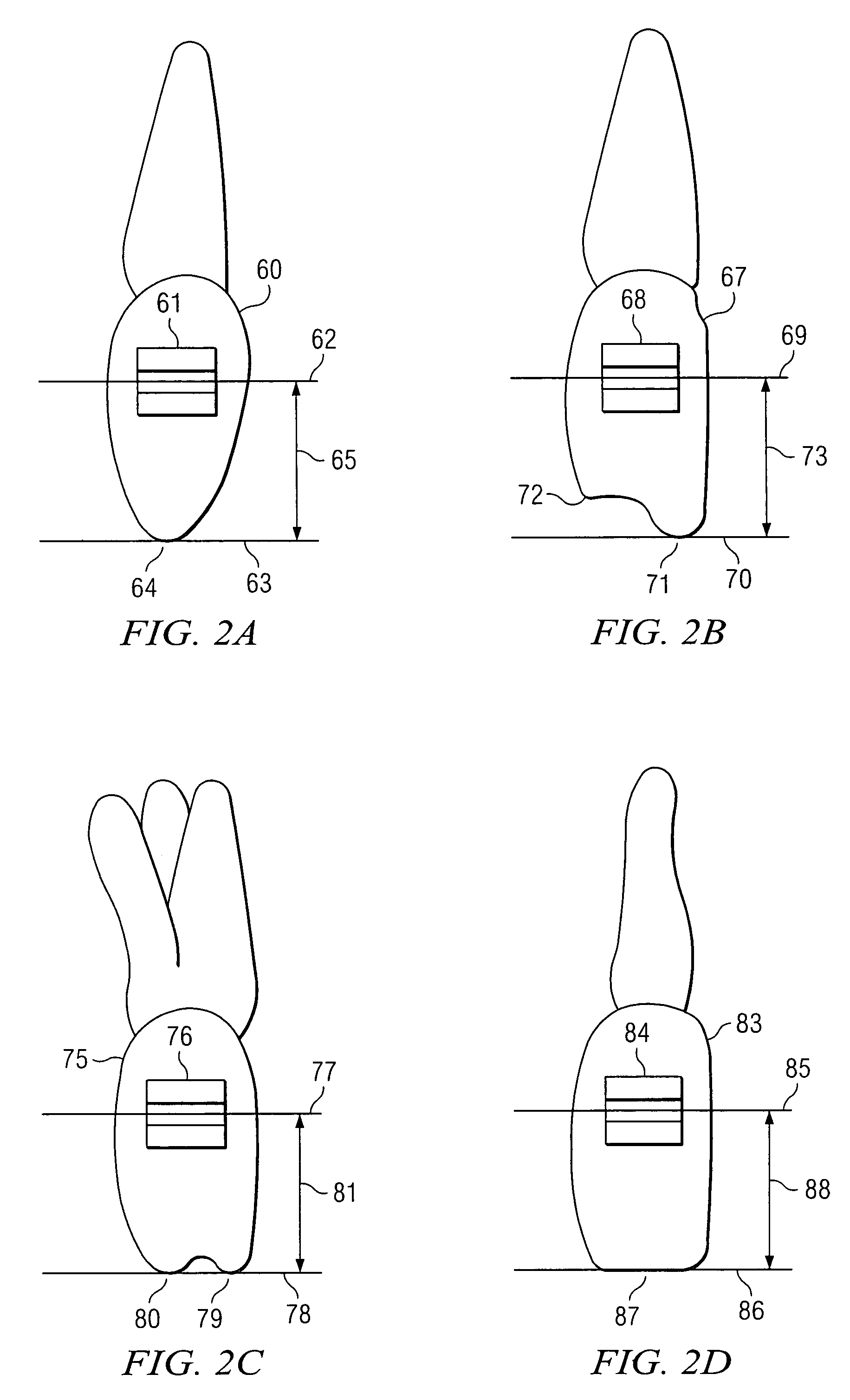
[0055]The present invention provides a method and apparatus for facilitating placement and evaluation of virtual appliances, such as virtual brackets, on virtual teeth of an orthodontic patient. The invention provides user selectable positioning references to facilitate initial automatic placement of virtual appliances on virtual teeth model. The appliance placement references can be used by a practitioner or a user in accordance with the practitioner's preferences and enable taking into account anatomical properties and features of patient's teeth while planning treatment. Once the virtual appliances are placed on the virtual teeth using the placement references a easy to use capability is provided for making adjustment of the virtual appliance placement. This invention enables proper planning of treatment for orthodontic patients. For an orthodontic patient suffering from a malocclusion treated by bonding brackets to the surface of the patient's teeth and placing archwires in the ...


PUM


Abstract

A method and apparatus for facilitating placement and evaluation of virtual appliances on virtual teeth of an orthodontic patient are described. Positioning references comprising bracket height, occlusal plane, or any arbitrary plane are provided to facilitate desired placement of virtual appliances on virtual teeth model. The process can be applied with any dentition state of a patient such as malocclusion, target state from treatment, or intermediate monitored state during the course of a treatment. An unified workstation for treatment planning provides the computer software tools for verification, simulation and evaluation of the virtual appliance placement. The process enables proper planning of treatment for an orthodontic patient suffering from malocclusion involving bonding of virtual brackets to the surface of the patient's virtual teeth with archwires placed in the slots of the brackets, so as to realize the desired results from the treatment in the most desired manner.

Description

CROSS-REFERENCE TO RELATED APPLICATIONS[0001]This application is a continuation-in-part application of the following U.S. patent applications:[0002]Ser. No. 10 / 684,252 filed Oct. 9, 2003, pending, which is a continuation of Ser. No. 09 / 834,412 filed Apr. 13, 2001 now issued as U.S. Pat. No. 6,632,089, which is a continuation-in-part of Ser. No. 09 / 560,640 filed Apr. 28, 2000 now abandoned, pending, which is a continuation in part of Ser. No. 09 / 451,609 filed Nov. 30, 1999 now issued as U. S. Pat. No. 6,250,918, and Ser. No. 09 / 560,130 filed Apr. 28, 2000 now U.S. Pat. No.6,736,638, pending. The entire contents of each of the above-referenced patent applications are incorporated by reference herein.BACKGROUND OF THE INVENTION[0003]A. Field of the Invention[0004]This invention relates generally to the field of computer-interactive methods for diagnosis, care and treatment planning, therapeutics and treatment monitoring in the medical arena, including orthodontics and in particular to ...

Claims


Application Information

Patent Timeline
Patent Type & Authority Patents(United States)
IPC IPC(8): A61C7/00A61C7/14A61C9/00A61C13/00A61F2/30
CPCA61C7/00A61C7/146A61C7/002A61F2002/30953A61C9/004A61C13/0004A61C9/0053A61C9/0086
Inventor SACHDEVA, ROHITSPORBERT, PEERMAETZEL, STEPHANIMGRUND, HANSSTRAUSS, CLAUDIAGETTO, PHILLIP
Owner ORAMETRIX
Why Eureka
Try Eureka