Particle vacuum intake control method and device and vacuum intake system

A technology of vacuum suction and control method, which is applied in the direction of transportation and packaging, conveying bulk materials, conveyors, etc., can solve the problem of low accuracy of particle quality, and achieve the effect of high accuracy, accuracy and consistency

Active Publication Date: 2020-01-17
克劳丽化妆品股份有限公司
View PDF12 Cites 0 Cited by
  • Summary
  • Abstract
  • Description
  • Claims
  • Application Information

AI Technical Summary

Problems solved by technology

[0006] The embodiment of the present application provides a particle vacuum suction control method, device and vac

Method used


Image

  • Particle vacuum intake control method and device and vacuum intake system
  • Particle vacuum intake control method and device and vacuum intake system
  • Particle vacuum intake control method and device and vacuum intake system

Examples


Embodiment 1

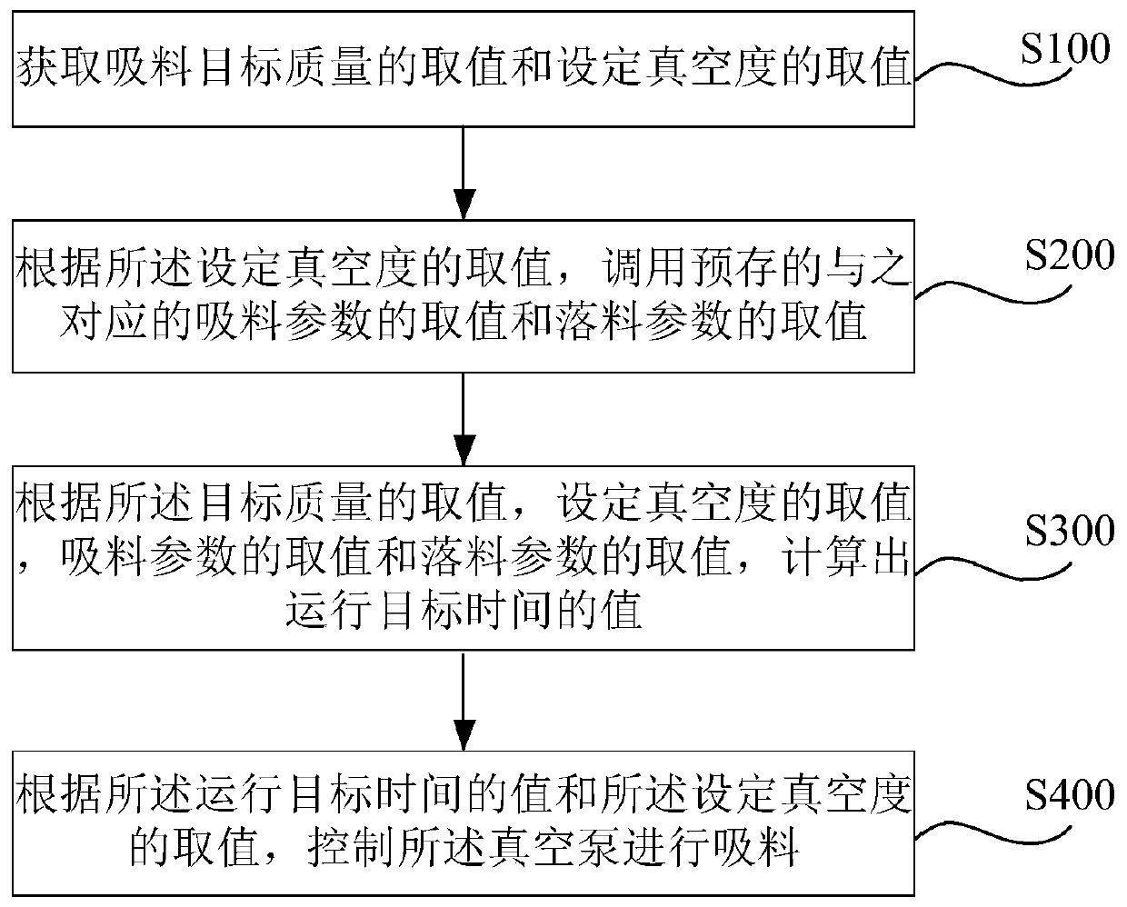
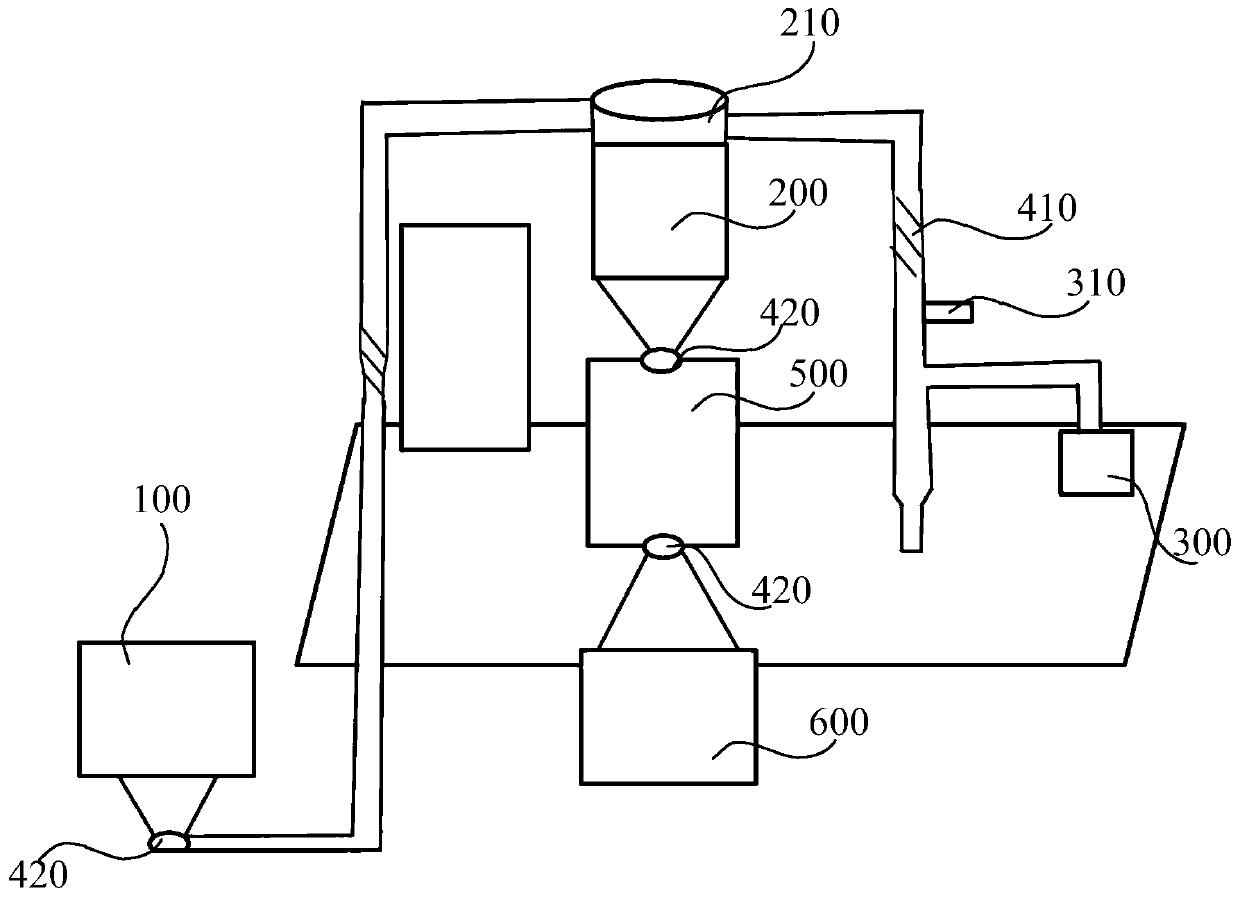
[0035] figure 1 It is a flow chart of a control method for particle vacuum suction according to an embodiment of the present application; figure 2 for use figure 1 Schematic diagram of the particle vacuum suction system shown in the control method of the particle vacuum suction. .

[0036] Such as figure 1 and figure 2 As shown, the control method of the particle vacuum suction of the embodiment of the present application includes:

[0037] Step S100: Obtain the target mass M of suction 目标 The value and the set vacuum degree P 设定 The value of; among them, the set vacuum degree P 设定 is the operating value set for the vacuum pump;

[0038] Step S200: According to the set vacuum degree P 设定 value, call the pre-stored corresponding suction parameter K 吸料 The value of and the blanking parameter K 落料 The value of; wherein, the value of the suction parameter is the vacuum pump with the set vacuum degree P 设定 The value of the negative pressure suction quality per unit of...

Embodiment 2

[0104] The particle vacuum suction control device of the embodiment of the present application includes:

[0105] The target acquisition module is used to obtain the suction target mass M 目标 The value and the set vacuum degree P 设定 The value of; among them, the set vacuum degree P 设定 is the operating value set for the vacuum pump;

[0106] Call module for setting the vacuum level P according to the 设定 value, call the pre-stored corresponding suction parameter K 吸料 The value of and the blanking parameter K 落料 The value of; wherein, the value of the suction parameter is the vacuum pump with the set vacuum degree P 设定 The value of the negative pressure suction quality per unit of time during vacuum suction, the blanking parameter K 落料 The value of is the quality of material sucked from the pipeline by unit negative pressure after the vacuum pump stops vacuuming;

[0107] Calculation module, for according to the target mass M 目标 value, set the vacuum degree P 设定 The value...

Embodiment 3

[0139] A particle vacuum suction control device according to an embodiment of the present application, comprising:

[0140] one or more processors;

[0141] storage means for storing one or more programs;

[0142] When the one or more programs are executed by the one or more processors, the one or more processors are made to implement the particle vacuum suction control method described in Embodiment 1.


PUM


Abstract

The embodiment of the invention provides a particle vacuum intake control method and device and a vacuum intake system. The control method comprises the steps that value of an intake target mass M target and value for setting a set vacuum degree P are obtained; setting of the set vacuum degree P is operation value set for a vacuum pump; according to the value for setting of the set vacuum degree P, a pre-stored value for intake of an intake parameter K and a pre-stored value for falling of a falling parameter K corresponding to the value for setting the set vacuum degree P are called; value ofthe intake parameter is the unit negative pressure intake mass of the vacuum pump at the unit time during vacuum intake at value set for the set vacuum degree P, and value for falling of the fallingparameter K is unit negative pressure intake mass from a pipeline through unit negative pressure after the vacuum pump stops vacuumizing; value of an operation target time T target is calculated; theoperation target time T target is vacuum pump operation target time; and according to value of the operation target time T target and value for setting the set vacuum degree P, the vacuum pump is controlled to carry out uptake. Through the method, the technical problem that accuracy of particle mass of vacuum intake is poor can be solved.

Description

technical field [0001] The present application relates to the technical field of vacuum suction, in particular, to a control method, device and vacuum suction system for particle vacuum suction. Background technique [0002] Using a vacuum feeder, a dust-free airtight pipeline conveying equipment that uses vacuum suction to convey granular and powdery materials, uses the air pressure difference between the vacuum and the ambient space to form gas flow in the pipeline to drive the movement of powdery materials, thereby completing the process. Powder transportation. [0003] In the existing technology, in the process of soap particle transmission and supply, there will be soap particles with unfixed weight remaining in the pipeline during the transmission process, resulting in the inability to accurately control the weight of the raw material soap particles in the cyclone separation silo, thus As a result, there is a slight difference in the content of the formula ingredients...

Claims


Application Information

Patent Timeline
IPC IPC(8): B65G53/24B65G53/34B65G53/36B65G53/66
CPCB65G53/24B65G53/34B65G53/36B65G53/66
Inventor 徐之伟徐晓平汪孔望
Owner 克劳丽化妆品股份有限公司
Why Eureka
Try Eureka