Perforating connector with sterile connection

a connector and sterile technology, applied in the field of perforating connectors, can solve the problems of high risk of injury to the personnel using the connector, pollute the needle, etc., and achieve the effect of high risk of injury

Inactive Publication Date: 2007-11-20
P2A MEDICAL
View PDF6 Cites 114 Cited by
  • Summary
  • Abstract
  • Description
  • Claims
  • Application Information

AI Technical Summary

Benefits of technology

[0008]It is necessary in particular to prevent any risk of the needle piercing the sealed enclosure in the absence of a container to be connected.
[0009]The invention also seeks to facilitate manipulation of the perforating connector, in particular to effect piercing by means of simple movements in axial translation.
[0012]The user can therefore control the relative movements that lead to piercing of both the foils and can in particular be sure of preventing piercing of the second foil during piercing of the first foil, and can pierce the second foil only after ensuring that the second container to be connected is present.

Problems solved by technology

The problem addressed by the invention is that of preventing, in the above kind of perforating connector, all risks of premature piercing of the sealed enclosure wall before placing the containers; premature piercing would not only cause pollution of the needle but also lead to a high risk of injury to the personnel using the connector.

Method used


Image

  • Perforating connector with sterile connection
  • Perforating connector with sterile connection
  • Perforating connector with sterile connection

Examples


Embodiment Construction

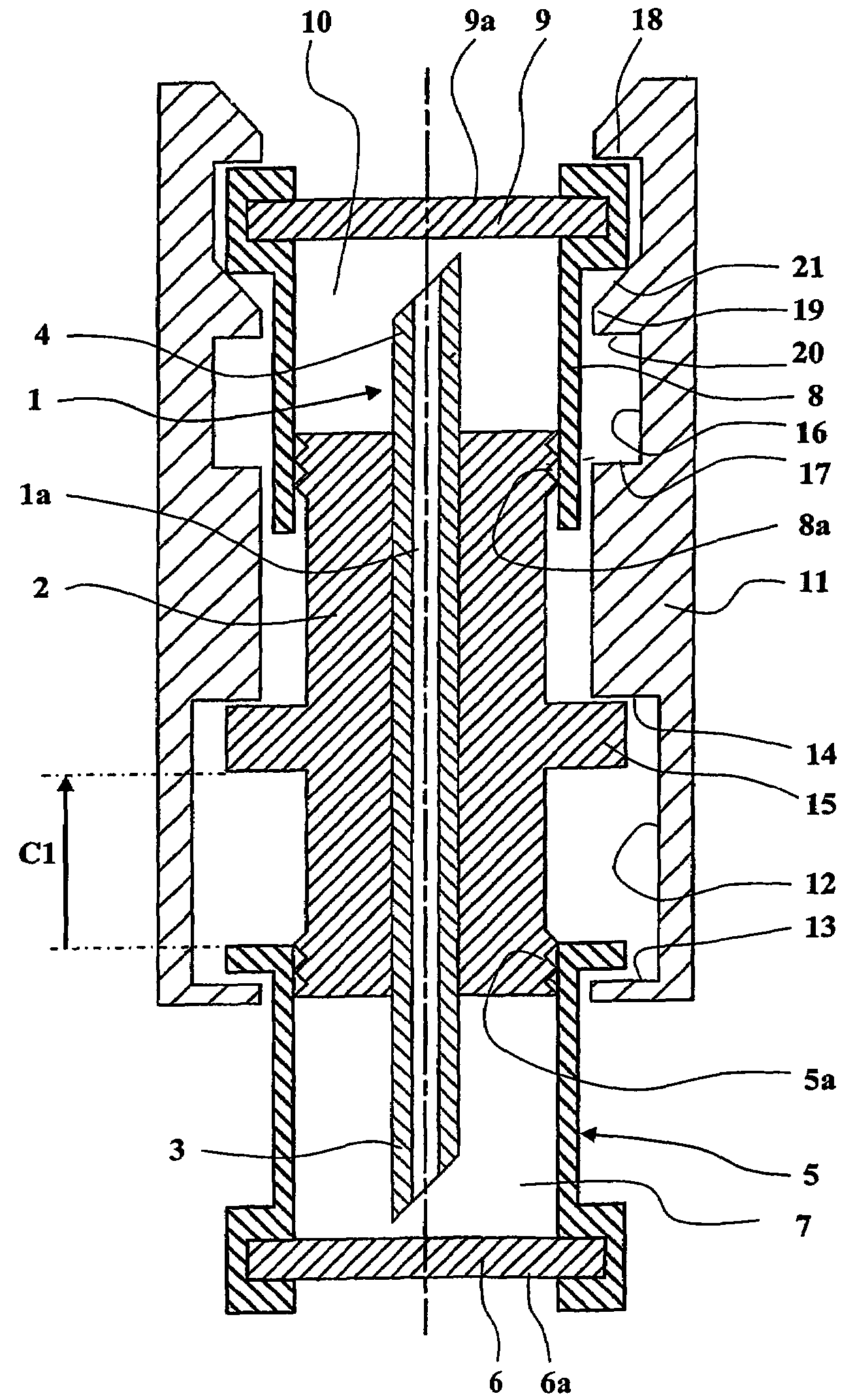
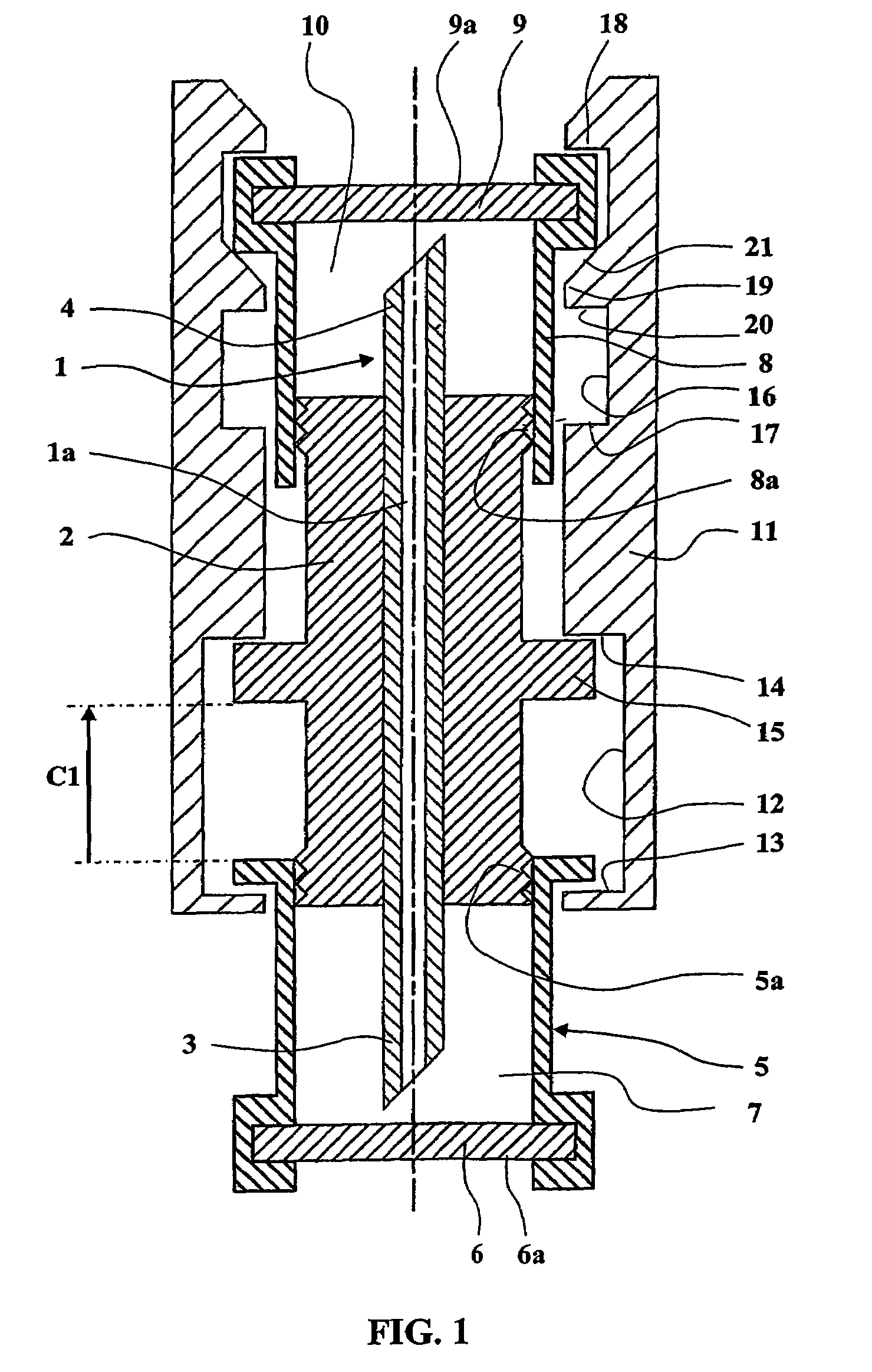
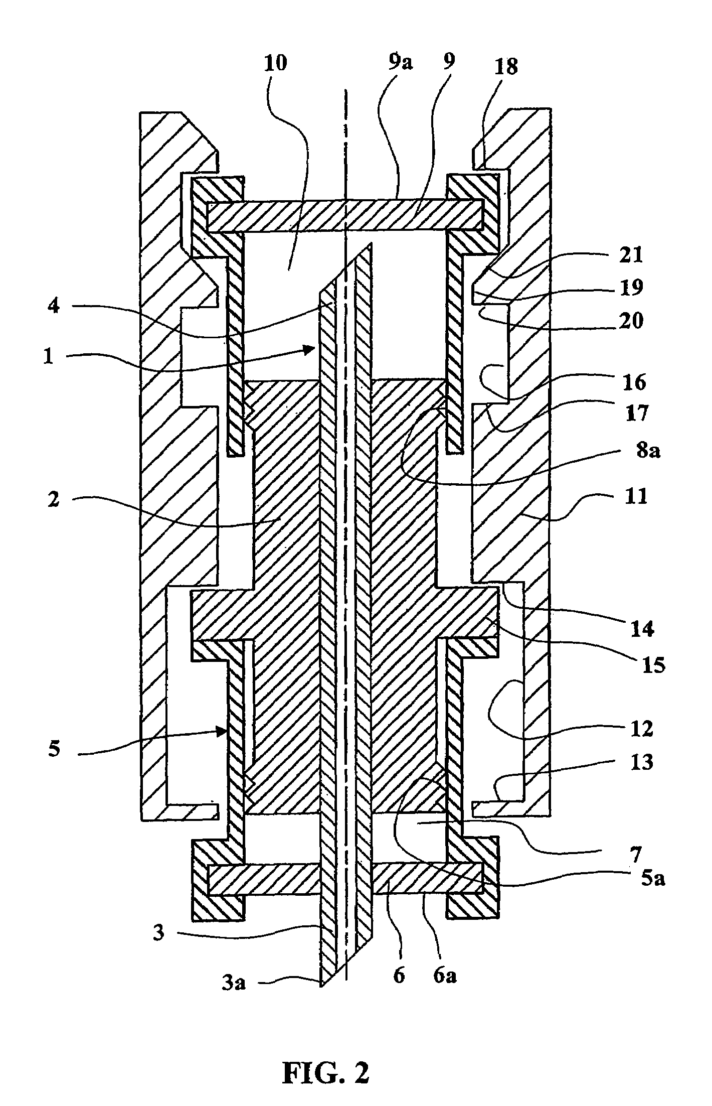
[0031]The embodiment of a perforating connector of the invention shown in the figures comprises a hollow needle 1 with an axial fluid passage 1a, and a needle support body 2 that surrounds and is fixed in a sealed manner to an intermediate section of the needle 1, and which leaves projecting a first end section 3 and a second end section 4 of the needle 1.

[0032]The first end section 3 of the needle 1 is surrounded by a first tubular receptacle 5 closed by a first foil 6. As a result, in an initial or transport position shown in FIG. 1, the first end section 3 of the needle 1 remains confined in a first cavity 7 delimited by the first foil 6, by the first tubular receptacle 5 and by the body 2.

[0033]Similarly, a second tubular receptacle 8 surrounds the second end section 4 of the needle 1 and is closed by a second foil 9. As a result, in an initial or transport position shown in FIG. 1, the second end section 4 of the needle 1 is confined in a second cavity 10 delimited by the secon...


PUM


Abstract

A connector according to the invention comprises a hollow needle fastened to a body. A first tubular receptacle provided with a first foil surrounds a first end section of the needle. A second tubular receptacle provided with a second foil surrounds a second end section of the needle. The tubular receptacles are able to slide on the body. The holding sleeve moves the body toward the first foil over a first piercing stroke to pierce it, and then moves the second foil toward the body over a second piercing stroke to pierce it. In this way there may be obtained simultaneous piercing of the foils and foils or stoppers of containers such as flasks or sachets pressed against the foils, to provide a connection under optimum conditions of sterility.

Description

TECHNICAL FIELD OF THE INVENTION[0001]The present invention concerns perforating connectors for connecting a first container and a second container together in order to pass a fluid between the two containers. The containers may be tubes, flasks, flexible wall sachets, having a mouth blocked by a foil through which a hollow needle can pass.[0002]The invention concerns more specifically a connector of the above kind provided with a hollow fluid passage needle adapted to pierce a first foil of the first container and a second foil of the second container in order to pass fluid through the axial passage of the needle between the two containers.[0003]Perforating connectors of the above kind have already been designed comprising a hollow fluid passage needle and a needle support body fixed in a sealed manner around an intermediate section of the needle to leave projecting first and second end portions of the needle adapted to pass through the foils of the containers.[0004]The ends of the...

Claims


Application Information

Patent Timeline
Patent Type & Authority Patents(United States)
IPC IPC(8): A61B19/00B65D41/62A61J1/00A61J1/20
CPCA61J1/2089A61J2001/2051A61J2001/2013A61J1/2051A61J1/2013A61J1/201
Inventor ORLU, ALAINCOMMARET, PIERRE-ANDRE
Owner P2A MEDICAL
Why Eureka
Try Eureka