Rotary switch

a rotary switch and switch technology, applied in the field of rotary switches, can solve the problems of extreme limitations, and achieve the effect of reducing the total space required for the rotary switch with the additional rotary button and better utilization of the available installation spa

Active Publication Date: 2007-11-20
TRW AUTOMOTIVE ELECTRONICS & COMPONENTS GMBH & CO KG
View PDF13 Cites 8 Cited by
  • Summary
  • Abstract
  • Description
  • Claims
  • Application Information

AI Technical Summary

Benefits of technology

[0003]The invention provides a rotary switch with a central handle which is rotatable about a central axis, a ring-shaped shield surrounding the handle, a rotary button which is arranged on the shield and is rotatable about an axis offset from and parallel to the central axis, and a potentiometer which is adjustable by means of the rotary button. The potentiometer is arranged radially spaced from the offset axis and is coupled with the rotary button by means of a gear. In this way, the total space required for the rotary switch with the additional rotary button can be distinctly reduced and the available installation space can be utilized better.
[0007]In a preferred embodiment of the invention, the gear is a step-up gear. In this way, a small amount of rotation may suffice for adjustment over a large range.
[0008]The rotary button may be coupled with a pin element which is fixedly connected with a first ratchet of the gear, thereby reducing the number of components. Moreover, the radial distance of the potentiometer from the rotary button can be bridged in a simple manner via the diameter of the first ratchet of the gear.
[0010]In an embodiment where the rotary switch comprises a printed circuit board, the rotary button is arranged above and the potentiometer is arranged underneath the printed circuit board. Not only a radial, but also an axial staggering between the potentiometer and the rotary button is achieved through this, whereby the small amount of available space can be utilized even better.

Problems solved by technology

This is extremely limited, particularly in vehicles for example on the instrument panel of a passenger car.

Method used


Image

  • Rotary switch
  • Rotary switch
  • Rotary switch

Examples


Embodiment Construction

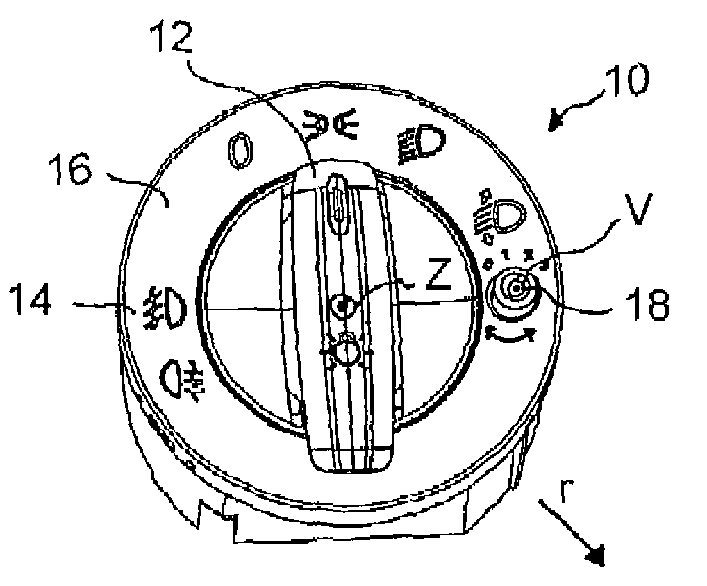
[0016]The rotary switch 10 shown in FIG. 1 operates light functions in a passenger car, although it is not limited to this application.

[0017]The rotary switch 10 comprises a central handle 12, here a rotary button, which is rotatable about a central axis Z into various discrete predetermined positions which are marked with the corresponding symbols 14 for the various settings of the vehicle lighting. The symbols 14 are applied onto a ring-shaped shield 16 surrounding the central handle 12, the shield 16 likewise being part of the rotary switch 10.

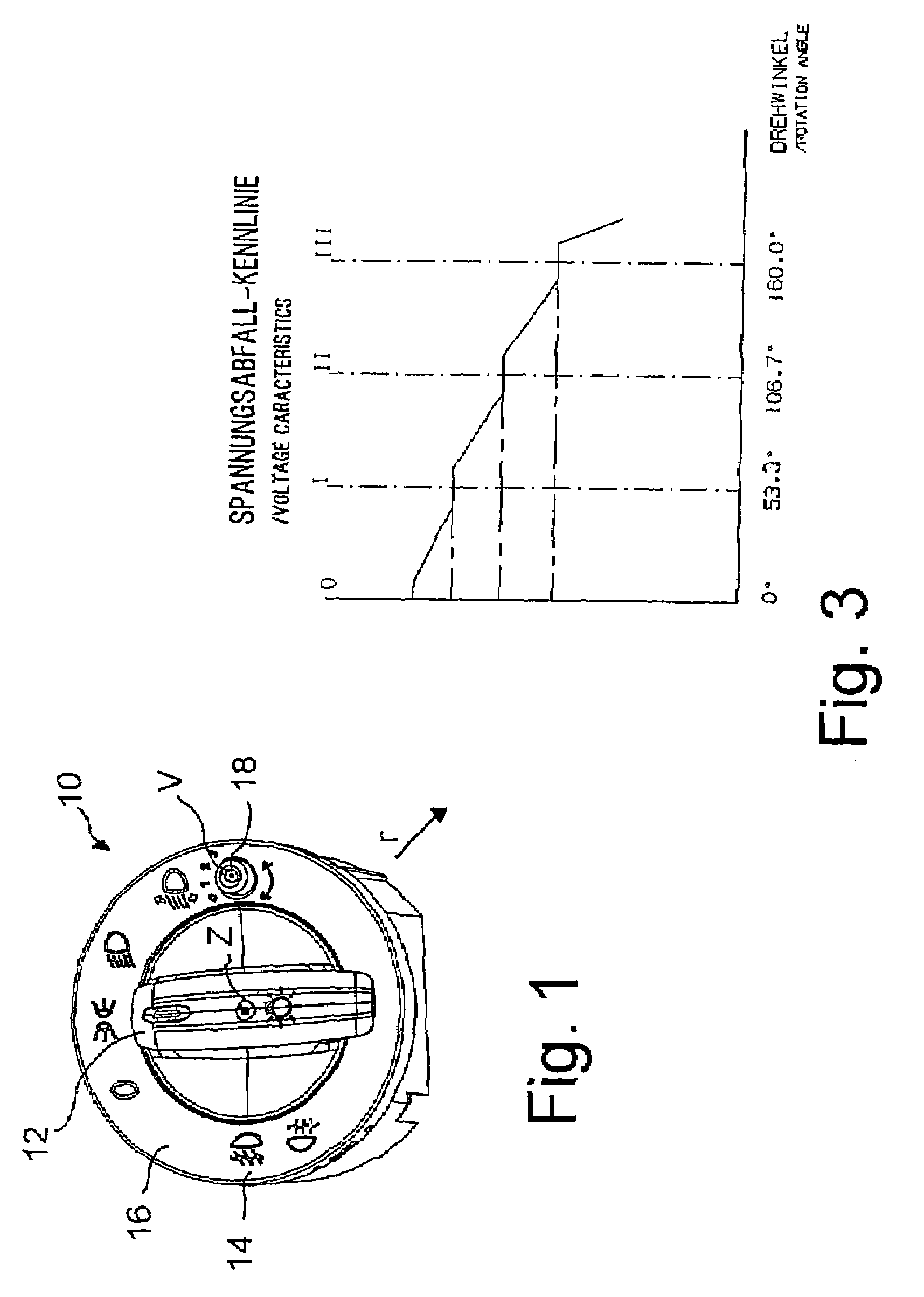
[0018]A rotary button 18 projects through the shield 16, the radial extent of the rotary button 18 being smaller than the radial dimension of the shield 16, so that the rotary button 18, as shown in FIG. 1, can be placed on the shield 16.

[0019]The rotary button 18 is mounted so as to be able to be retracted in a known manner. On axial pressure (into the plane of the drawing in FIG. 1), a lock, e.g. similar to a ballpoint pen mechanism, is r...


PUM


Abstract

A rotary switch is disclosed which has a central handle (12) which is rotatable about a central axis (Z), a ring-shaped shield (16) surrounding the handle (12), a rotary button (18) which is arranged on the shield (16) and is rotatable about an axis (V) offset from and parallel to said central axis (Z), and a potentiometer (28) which is adjustable by means of the rotary button (18).The potentiometer (28) is radially spaced from the offset axis (V), and is coupled with the rotary button (18) by means of a gear (24, 26). The potentiometer (28) is offset radially inwards from the offset axis (V) towards the central axis (Z).

Description

BACKGROUND OF THE INVENTION[0001]The invention relates to a rotary switch.[0002]When operating switches, it is sometimes comfortable for the user when related functions can be carried out by means of operating elements which are closely adjacent to each other. For example, an adjustment means for the illumination range, i.e. the angle of the headlights, is also to be provided in the immediate vicinity of a switch by which the various light functions of the vehicle are selected. In doing this, however, the available structural space must always be taken into account. This is extremely limited, particularly in vehicles for example on the instrument panel of a passenger car.SUMMARY OF THE INVENTION[0003]The invention provides a rotary switch with a central handle which is rotatable about a central axis, a ring-shaped shield surrounding the handle, a rotary button which is arranged on the shield and is rotatable about an axis offset from and parallel to the central axis, and a potentiom...

Claims


Application Information

Patent Timeline
Patent Type & Authority Patents(United States)
IPC IPC(8): H01H19/00H01H19/14H01H21/00H01H3/08
CPCH01C10/14H01H3/0213H01H19/14H01H2003/085H01H25/06
Inventor BORNHORST, DIETERMUELLER, KLAUSFROHNE, HANS-JOACHIM
Owner TRW AUTOMOTIVE ELECTRONICS & COMPONENTS GMBH & CO KG
Why Eureka
Try Eureka