
Apparatus for removal of minute particles from a surface using thermophoresis to prevent particle redeposition

a technology of thermophoresis and surface removal, which is applied in the direction of cleaning using liquids, instruments, manufacturing tools, etc., can solve the problems of contamination that can be a very significant problem, local heating and possible damage, and particle contamination of surfaces

Inactive Publication Date: 2007-11-20
ARKANSAS STATE UNIV
View PDF21 Cites 6 Cited by
  • Summary
  • Abstract
  • Description
  • Claims
  • Application Information

AI Technical Summary

Problems solved by technology

Particle contamination of surfaces is a concern in many areas of technology.
Two areas where such contamination can be a very significant problem are optics, particularly those with critical optical surfaces, and electronic device fabrication.
As minute particles contaminate optical surfaces, they can serve as sinks for optical power incident on the optical surfaces and thus produce localized heating and possible damage.
In the electronics industry, particle contamination is an important factor in the manufacture of high density integrated circuits.
Even in relatively conventional technology using micron or larger circuit patterns, submicron size particle contamination can be a problem.
Today the technology is progressing into submicron pattern sizes, and particle contamination is even more of a problem.
Contaminant particles larger than roughly 10% of the pattern size can create damage, such as pinholes, which interfere with fabrication processes (such as etching, deposition and the like), and defects of that size are a sufficiently significant proportion of the overall pattern size to result in rejected devices and reduced yield.
In spite of that, the manufactured devices can become contaminated, not only by contaminants carried in the air, but also by contaminants created by the processes used to fabricate the devices.
Removal of such small particles can potentially damage the substrate.
In general, it has been found that submicron particles are the most difficult to remove.
Many of the processes developed to clean integrated circuits, such as ultrasonic agitation, are not effective for micron and submicron particles and indeed, sometimes add contaminants to the substrate.
One of the challenges of LAPR and other particle removal methods is keeping the particles from redepositing on the surfaces, particularly for very small particles that are not significantly affected by gravity.

Method used


Image

  • Apparatus for removal of minute particles from a surface using thermophoresis to prevent particle redeposition
  • Apparatus for removal of minute particles from a surface using thermophoresis to prevent particle redeposition
  • Apparatus for removal of minute particles from a surface using thermophoresis to prevent particle redeposition

Examples


Embodiment Construction

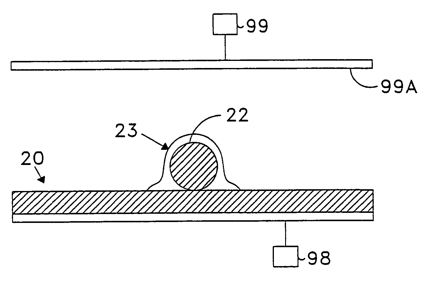
[0026]Co-pending U.S. application Ser. No. 09 / 909,993, which is hereby incorporated by reference, discusses and proposes methods and apparatus that efficiently remove minute particles from the surface of a substrate. The methods and apparatus according to the invention of Co-pending U.S. application Ser. No. 09 / 909,993 overcome the shortcomings of the prior art. However, as discussed above, one of the challenges of LAPR and other particle removal methods is keeping the particles from redepositing on the surfaces, particularly for very small (for example, micrometer and nanometer size) particles that are not significantly affected by gravity.

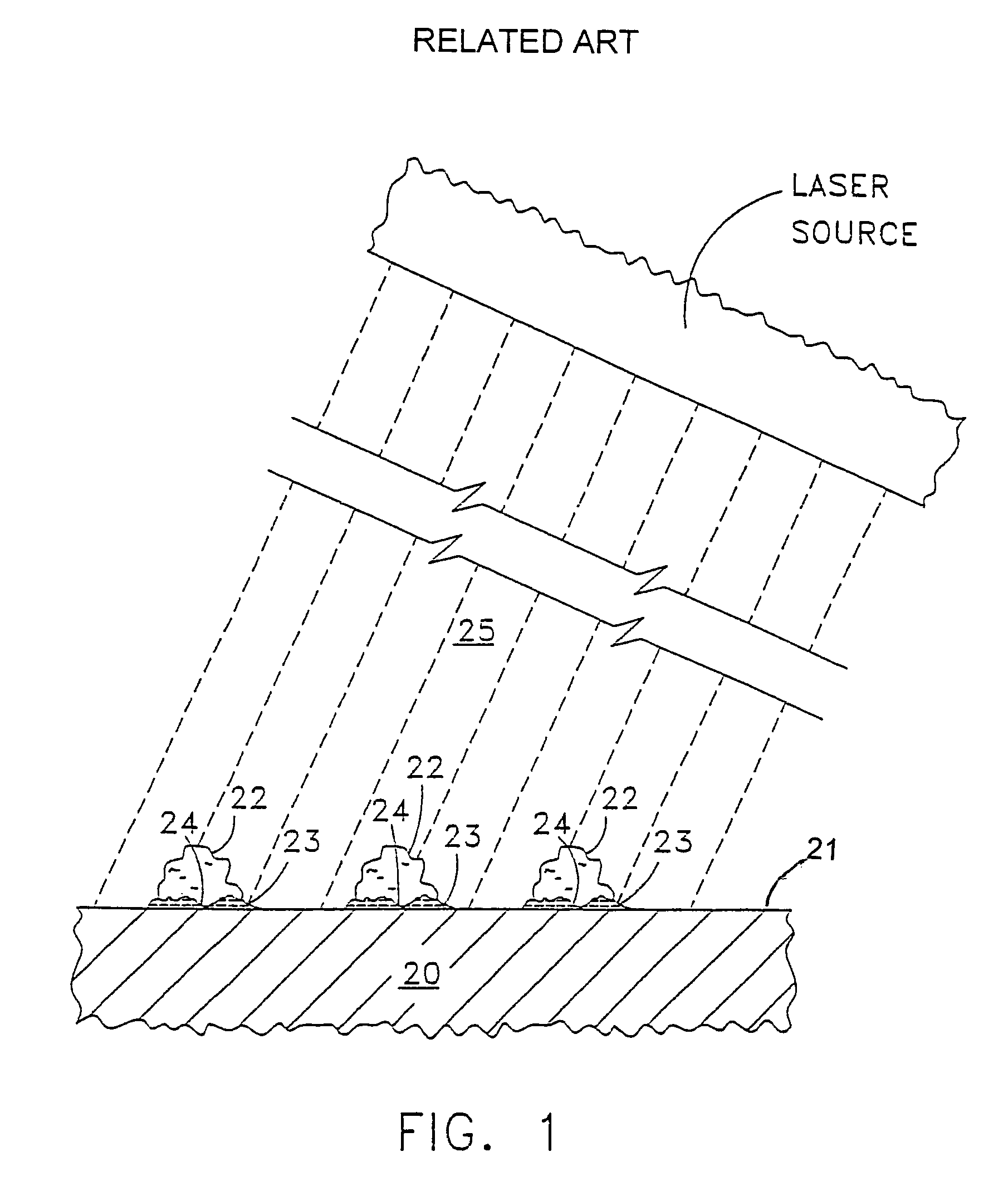
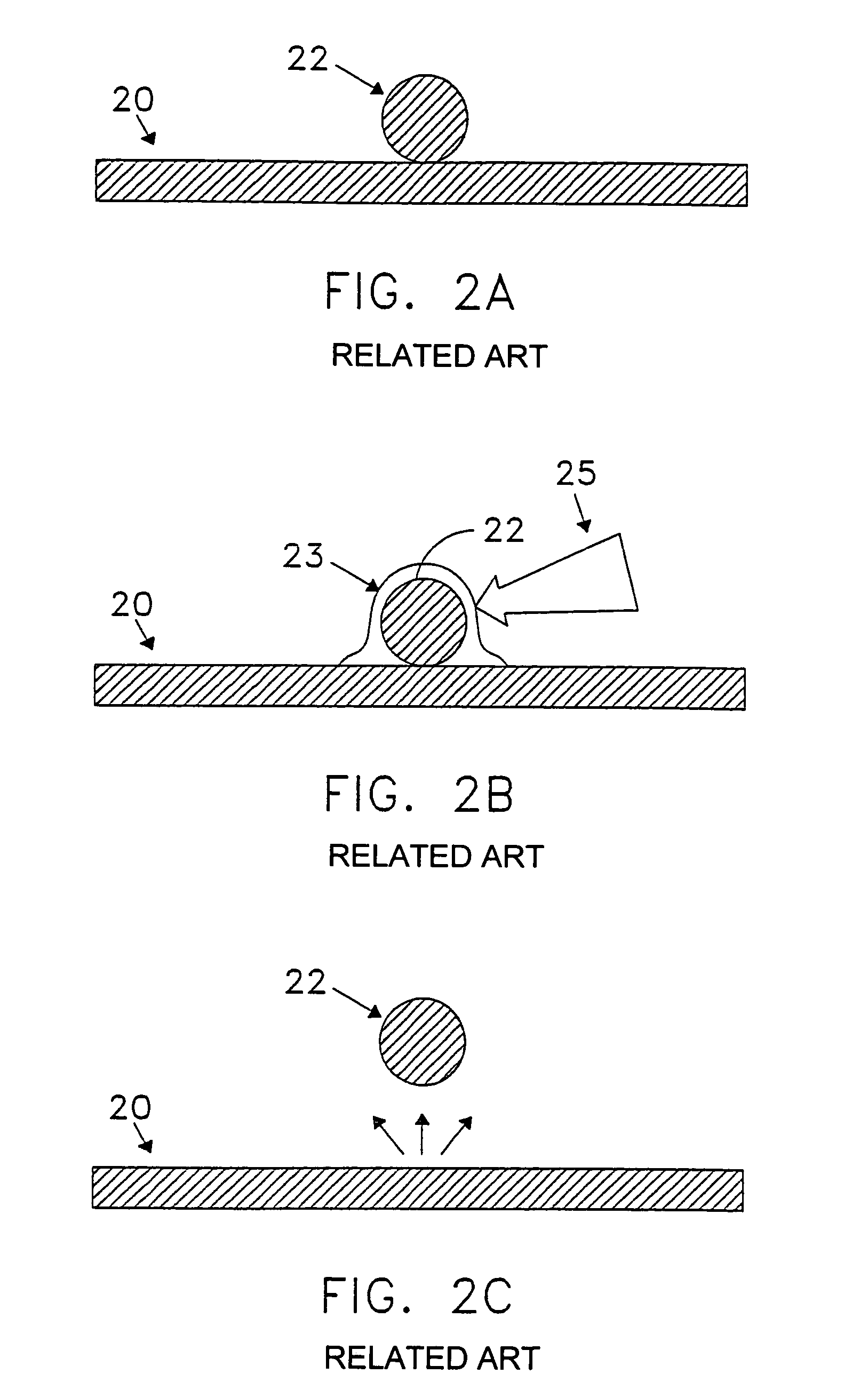
[0027]As previously discussed, FIG. 1 shows, in cross-section, a portion of a substrate 20 bearing contaminant particles 22 which are adhered to a surface 21. The particles 22 are bound to the surface 21 by any of a number of forces. The particles are deposited usually by a complex process which may include diffusion, sedimentation, inertia, and ...


PUM

PropertyMeasurementUnit
sizeaaaaaaaaaa
sizeaaaaaaaaaa
pressureaaaaaaaaaa

Abstract

A method and apparatus for removing minute particles from a surface of a sample are provided that prevent redeposition of the particles onto the surface. By combining thermophoresis with laser assisted particle removal (LAPR), the methods and apparatus remove minute particles (for example, micrometer and nanometer sizes) and assure that they will not redeposit.

Description

[0001]This application is a Continuation of prior application No. 09 / 909,992, filed Jul. 23, 2001, now U.S. Pat. No. 6,805,751, which is hereby incorporated by reference.BACKGROUND OF THE INVENTION[0002]1. Field of the Invention[0003]The present invention relates to a method and apparatus for removing minute particles from a surface. More particularly, the invention relates to a method and apparatus for removing minute particles from a surface using thermophoresis to prevent particle redeposition.[0004]2. Background of the Related Art[0005]Particle contamination of surfaces is a concern in many areas of technology. Two areas where such contamination can be a very significant problem are optics, particularly those with critical optical surfaces, and electronic device fabrication. The effect of contaminants on critical optical surfaces (coated or uncoated, dielectric or metal), for example in high power laser optics, can lead to increased optical absorption and a decreased laser damag...

Claims


Application Information

Patent Timeline
Patent Type & Authority Patents(United States)
IPC IPC(8): B23K26/00B08B7/00G03F1/82
CPCG03F1/82B08B7/0042
Inventor ALLEN, SUSAN DAVIS
Owner ARKANSAS STATE UNIV
Learn More