

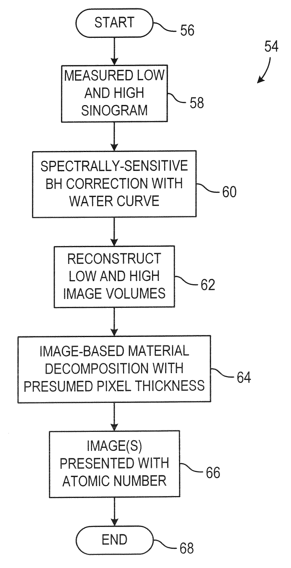
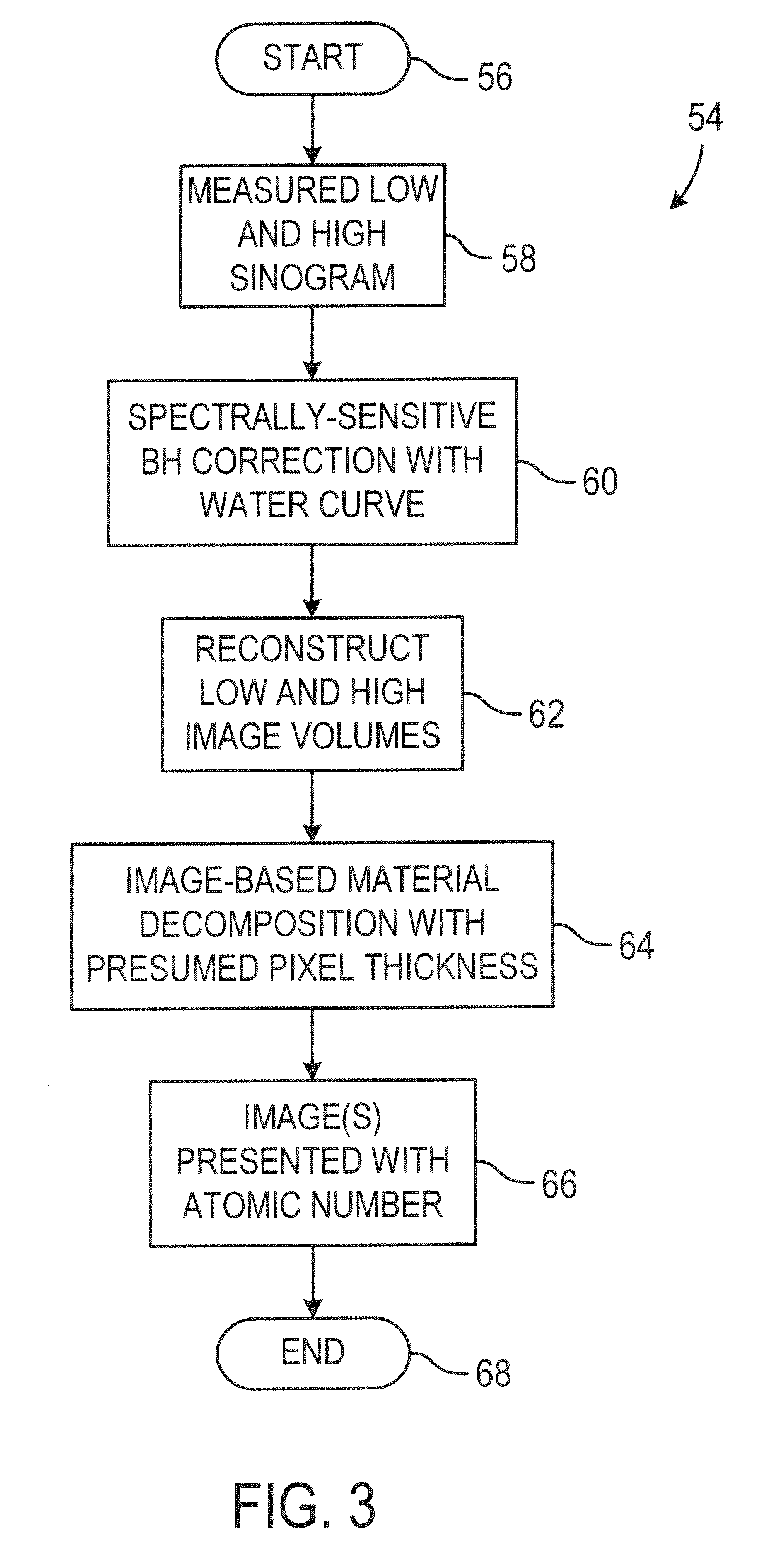
Image-based material decomposition
a material decomposition and image technology, applied in the field of diagnostic imaging, can solve problems such as errors in the material decomposition sinogram, beam hardening artifacts in the image, and beam hardening errors in the imag
- Summary
- Abstract
- Description
- Claims
- Application Information
AI Technical Summary
Benefits of technology
Problems solved by technology
Method used
Image

Examples
Embodiment Construction
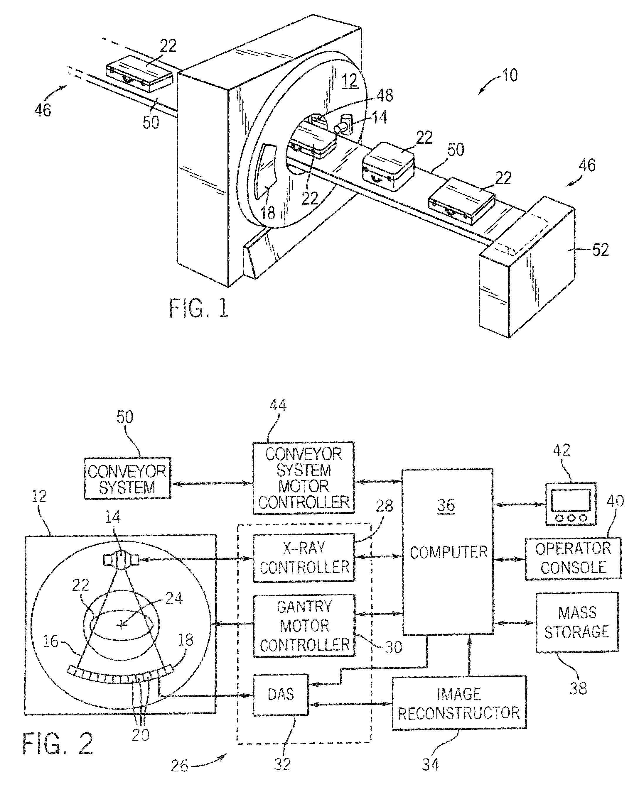
[0025]Referring to FIGS. 1 and 2, a computed tomography (CT) imaging system 10 is shown as including a gantry 12 representative of a “third generation” CT scanner for scanning luggage, parcels, and packages. Gantry 12 has an x-ray source 14 that projects a beam of x-rays 16 toward a detector array 18 on the opposite side of the gantry 12. The x-ray source is preferably a single-anode x-ray source. Detector array 18 is formed by a plurality of detectors 20 which together sense the projected x-rays that pass through an object 22. Each detector 20 produces an electrical signal that represents the intensity of an impinging x-ray beam and hence the attenuated beam as it passes through the patient 22. It is contemplated that each detector 20 may be an energy integrating detector or a photon counting energy discriminating detector. During a scan to acquire x-ray projection data, gantry 12 and the components mounted thereon rotate about a center of rotation 24.
[0026]Rotation of gantry 12 an...
PUM
| Property | Measurement | Unit |
|---|---|---|
| angle | aaaaa | aaaaa |
| fan angle | aaaaa | aaaaa |
| thickness | aaaaa | aaaaa |
Abstract
Description
Claims
Application Information