
Link adaptation process

a technology of adaptation process and link, applied in the field of link adaptation process, can solve the problems of difficult to understand how to effectively use the criteria of sinr and ber, and the relationship between sinr and ber is not straightforward, and achieve the effect of easy computation

Inactive Publication Date: 2007-11-20
MITSUBISHI ELECTRIC CORP
View PDF4 Cites 6 Cited by
  • Summary
  • Abstract
  • Description
  • Claims
  • Application Information

AI Technical Summary

Benefits of technology

[0022]The aim of the invention is to provide a link adaptation process that can be computed easily and which uses the channel profile properties without being dependent on the a-priori knowledge of the fading channel.

Problems solved by technology

Besides, the relation between the SINR and the BER is not straightforward because it is also very dependent on the transmission channel.
The problem mentioned in this document is how to predict the PER or BER taking into account SINR and channel statistics.
However, the results presented in this article on FIG. 10 are only for the particular channel A of Hiperlan / 2 standard and therefore it is difficult to understand how this criteria can be effectively used to become independent from knowledge a-priori of the fading channel.

Method used


Image

  • Link adaptation process
  • Link adaptation process
  • Link adaptation process

Examples


first embodiment

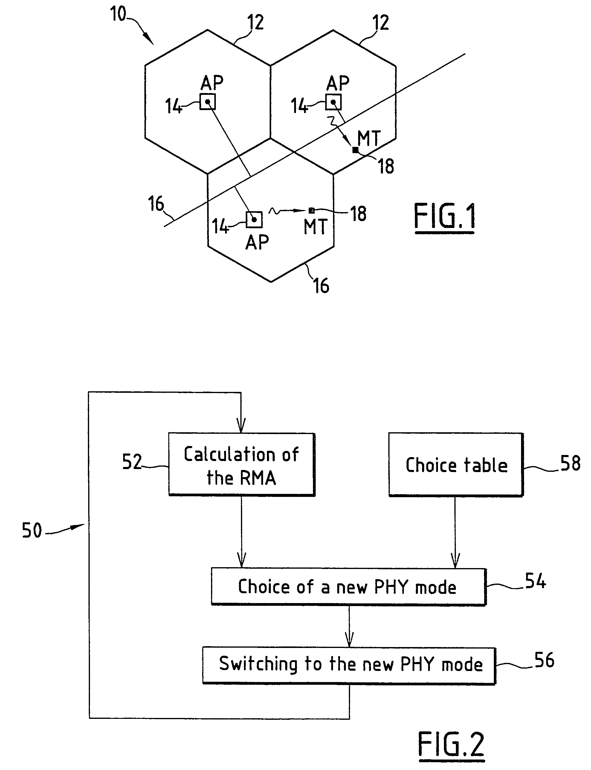
[0126]According to the invention, the RMA is calculated for each burst by using the preamble structure that precedes each data burst.

[0127]The preamble is a know sequence and therefore it is easy to compare the observed sequence with the ideal sequence as described in the equation of the received modulation accuracy.

In that case,

[0128]Nf is the number of frames for the measurement (for instance Nf=20 frames enables a good averaging).

[0129]Np is the number of symbols composing the preamble of each burst (for instance 2 OFDM symbols in the case of Hiperlan2 preambles).

[0130]Kc is the number of frequencies composing the preamble (for instance 52 sub-carriers in the case of Hiperlan2 preambles).

[0131]Ns is the number of space diversity composing the preamble (for instance 1 or 2 in the case of Hiperlan2 preambles).

[0132]P0 is the average power of the constellation (usually P0=1 when an receiving or transmitting power control is employed).

[0133]In other words, (I0(t,f,s),Q0(t,f,s)) in th...

second embodiment

[0140]According to the invention, the RMA is calculated by computing on the payload part of the bursts.

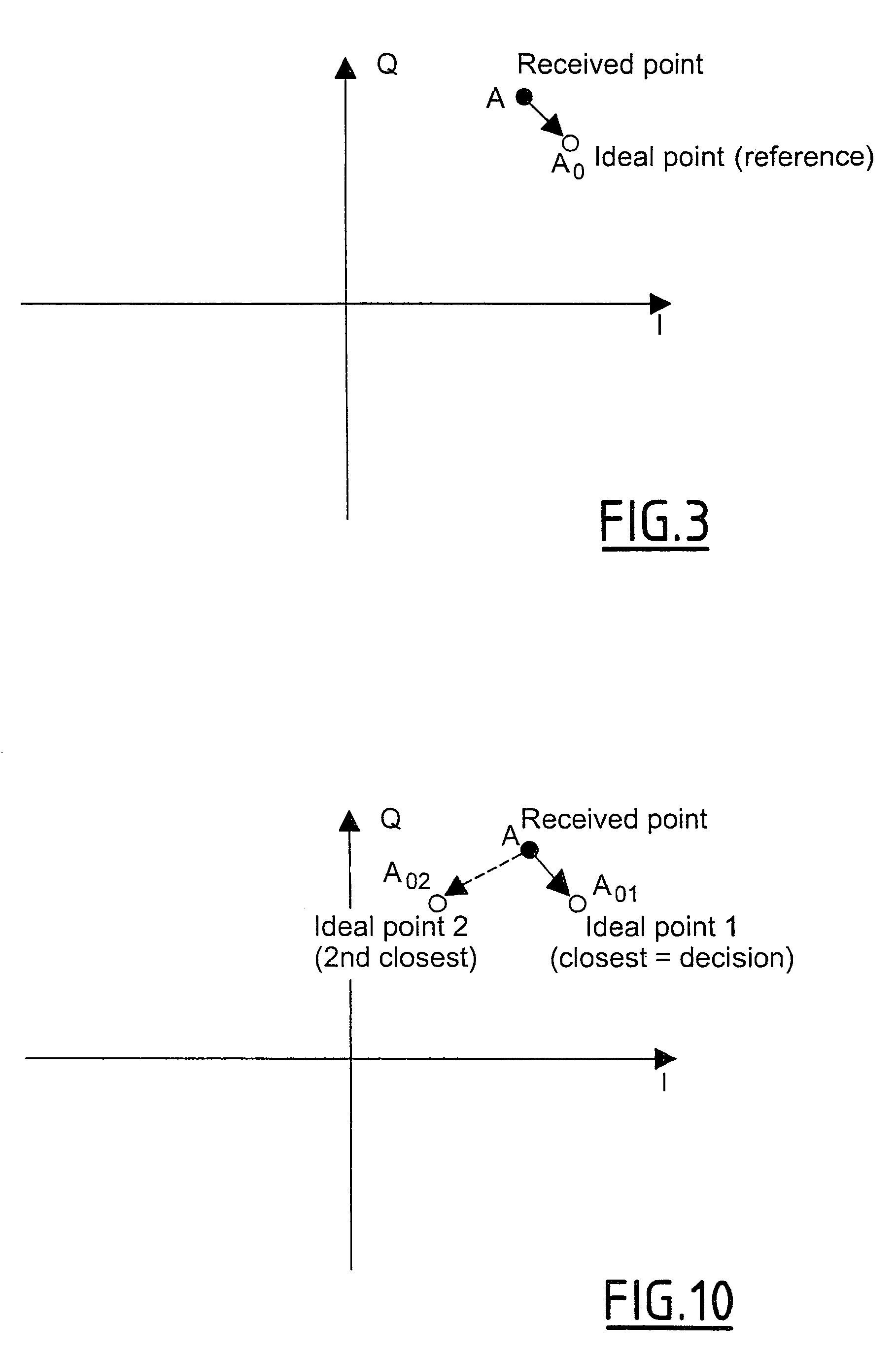
[0141]In that case, (I0(t,f,s),Q0(t,f,s)) is obtained from taking a decision on (I(t,f,s),Q(t,f,s)), the observed point after equalisation. Such calculation is more complex since it requires to take a decision on unknown payload symbols before computing the RMA. Taking a decision requires to determine the closest ideal point from the received point:

[0142]As shown on FIG. 10, a received point can be linked to several close points as Ideal point 1 or Ideal point 2.

[0143]For example the chosen ideal point is defined as the point defining with the received point a shorter length according to a known metric.

[0144]For example, the metric is defined as:

Δ2(t,f,s)=(I(t,f,s)−I0(t,f,s))2+(Q(t,f,s)−Q0(t,f,s))2

[0145]Therefore, such procedure requires more computational complexity and should be used only if necessary.

[0146]In other words, in that case:

(I0(t,f,s),Q0(t,f,s))=(Î(t,f,s),{circumflex ...


PUM


Abstract

The link adaptation process for selecting a physical layer mode used on a radio link for transmitting symbols of a message between two stations of a wireless communication system among a set of potential physical layer modes comprises the steps of: —evaluating the current radio link conditions; and switching from a current physical layer mode to another physical layer mode by applying a criteria depending on the evaluated current radio link conditions. The evaluation step of the current radio link conditions comprises the calculation of a received modulation accuracy (RMA) for at least a part of the message, the received modulation accuracy (RMA) being de\-fined as the inverse of the expectation of a quadratic error for a predetermined number of symbols between demodulated received symbol values and ideal symbol values and in that the criteria is at least partially dependent on the calculated received modulation accuracy (RMA).

Description

BACKGROUND OF THE INVENTION[0001]1. Field of the Invention[0002]The invention concerns a link adaptation process.[0003]2. Discussion of the Related Art[0004]In known wireless communication systems, information are transmitted via the air interface between two entities of the systems via the physical layer following the ISO-OSI model.[0005]Depending on the current radio link conditions, several physical layer modes can be selected. A physical layer mode specifies a coding rate and modulation conditions. A link adaptation process is implemented for selecting the physical layer modes (PHY modes).[0006]For example, such a link adaptation process is necessary in a High PErformance Radio Local Area Network type 2 (HIPERLAN / 2) standard. In the following, the HIPERLAN / 2 standard will be used often as an example of framework to describe the context of the invention. However, the field of application of this invention goes beyond the boundaries of the HIPERLAN / 2 standard and can be considered...

Claims


Application Information

Patent Timeline
IPC IPC(8): H04B17/00H04B7/26H04L27/00H04J11/00H04L1/00H04L1/20H04L27/26
CPCH04L1/0003H04L1/0009H04L1/206H04L27/2601H04L1/0015H04L27/2602
Inventor PENTHER, BERTRAND
Owner MITSUBISHI ELECTRIC CORP
Learn More