
Mechanism for managing execution environments for aggregated processes

a technology for managing execution environments and processes, applied in the field of distributed computing, can solve the problems of affecting the efficiency of execution environments, and affecting the performance of execution environments, etc., and achieves the effect of reducing the number of different tasks that perform the work, and reducing the complexity of execution environments

Inactive Publication Date: 2007-11-20
CADENCE DESIGN SYST INC
View PDF25 Cites 31 Cited by
  • Summary
  • Abstract
  • Description
  • Claims
  • Application Information

AI Technical Summary

Benefits of technology

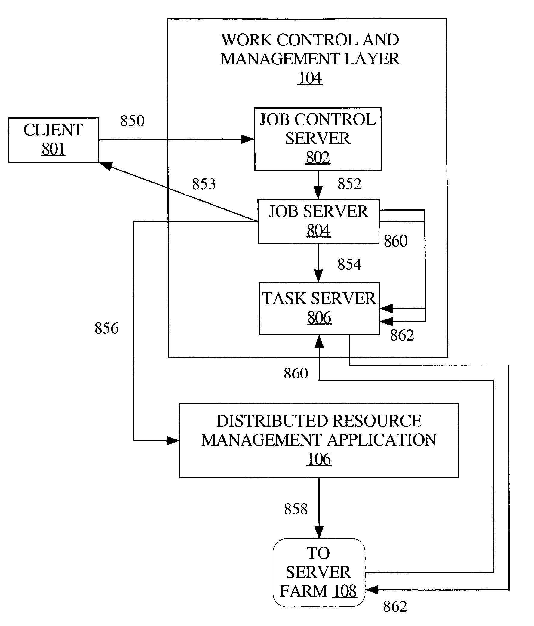
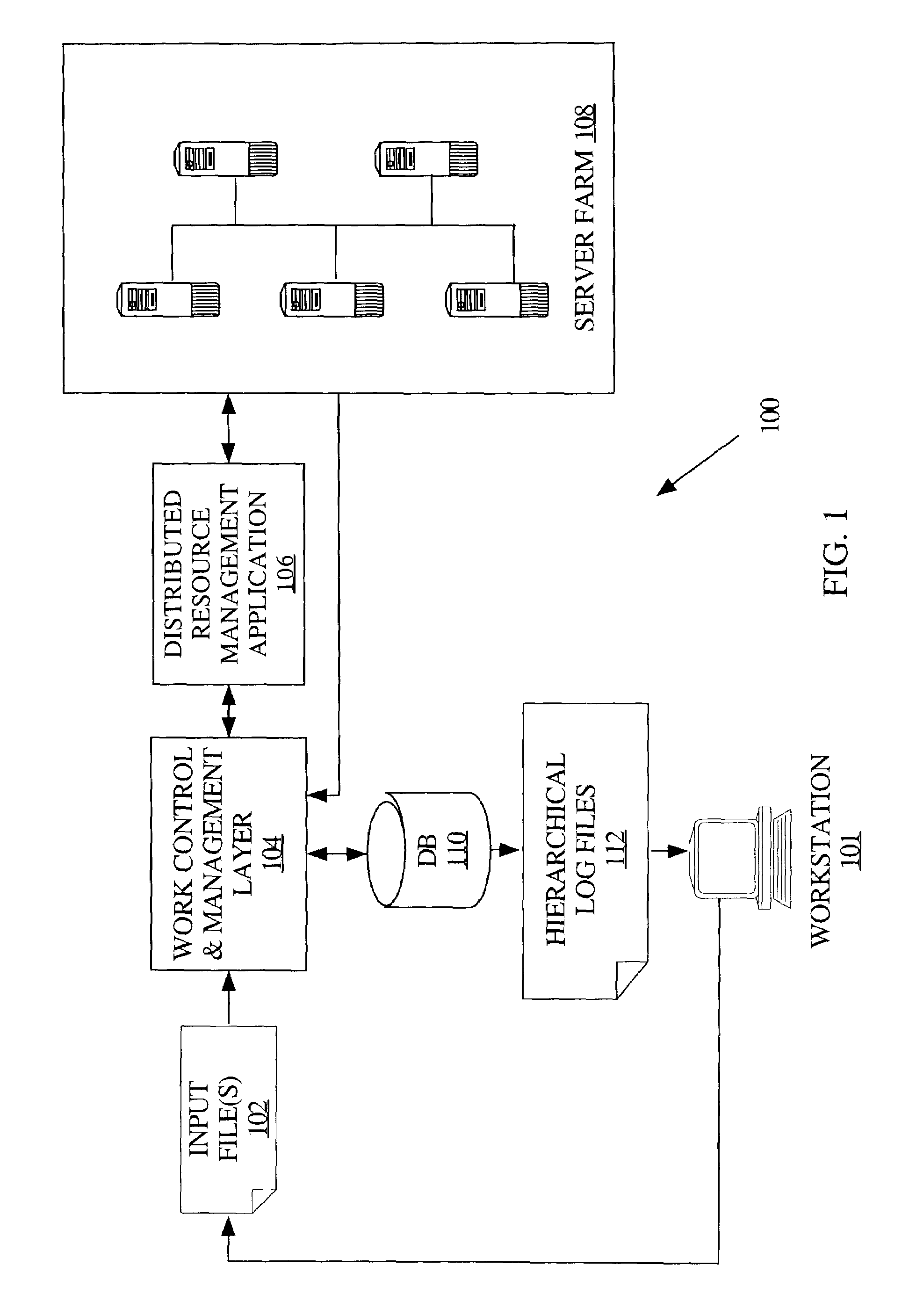
[0107]The persistent distributed object architecture provides a platform-independent solution which decreases the complexity of an implementation of the system and methods described herein. Since the state of the objects which represent the processes running on a server farm are critical, the state of the objects in this framework are persistent, that is, they are stored in a non-volatile medium. Since process architecture within a server farm can change dependent on the size and type of server farm being employed, the inter-process communication utilized by the persistent distributed object architecture is independent of the process architecture of a given server farm.
[0183]In one embodiment, the job ID has a hierarchical configuration resembling a pathname, wherein each level of the job ID corresponds to a level of a hierarchy. The hierarchy embodied in the job ID mirrors the job aggregation hierarchy specified in the work request. For example, a job ID can be configured as: group.usernamejobnumber.sub-job. Thus, components of the job ID reference a process specified in a corresponding work request. Furthermore, successive runs of a job are incrementally identified. Incrementally identifying successive runs of a job facilitates statistical analysis of successive corresponding job runs. The job ID structure also drives the structure, described above, of the log report information presented to a user.

Problems solved by technology

In such a scenario, a machine going off-line can result in having to modify many scripts that were tailored to that machine, platform, or environment.
Not only does this manner of operating contribute to a waste of resources, such as unused processor capacity, but also the task of managing the large number of scripts and the computing resources on which the scripts run becomes a non-trivial, highly complex effort.
In the context of complex, interdependent software development tasks running together as a unit of work, the number of different tasks that perform the work can be enormous.
Since runtime and termination statistics are usually generated for each executable unit of work, a corresponding log file can likewise be enormous.
Consequently, such a log file is not easy to analyze and to glean information from.
Such a manual process is not an efficient use of time and resources.

Method used


Image

  • Mechanism for managing execution environments for aggregated processes
  • Mechanism for managing execution environments for aggregated processes
  • Mechanism for managing execution environments for aggregated processes

Examples


Embodiment Construction

[0021]A mechanism for managing execution environments for aggregated computing processes is described herein. In the following description, for the purposes of explanation, numerous specific details are set forth in order to provide a thorough understanding of the present invention. It will be apparent, however, that the present invention may be practiced without these specific details. In other instances, well-known structures and devices are shown in block diagram form in order to avoid unnecessarily obscuring the present invention.

Overview

[0022]According to one aspect, workspace definitions, which define an execution environment, can be associated with jobs. A work request is processed to automatically determine that tasks that are progeny of a given job inherit the association with the workspace definition, and therefore, that the tasks should be executed using the execution environment defined in the workspace definition. However, different execution environments can be defined...


PUM


Abstract

Workspace definitions, which define an execution environment, can be associated with jobs. A work request is processed to automatically determine that tasks that are progeny of a given job inherit the association with the workspace definition, and therefore, that the tasks should be executed using the execution environment defined in the workspace definition. However, different execution environments can be defined for progeny of a given parent job, essentially overriding the inheritance from the parent job. According to an embodiment, a set of resources associated with an execution environment is configured such that the resources are accessible by two or more computers of a group of networked computers, such as a server farm, without requiring configuring duplicate sets of the resources. Furthermore, in a server farm computing environment, an execution environment associated with one or more jobs is not reliant on being created on any given computer of the server farm.

Description

CROSS REFERENCE TO RELATED APPLICATIONS[0001]This application claims the benefit of priority to U.S. Provisional Patent Application No. 60 / 342,630 entitled “Server Farm Management Mechanism”, filed Dec. 20, 2001; and is related to U.S. patent application Ser. No. 10 / 247,970 now U.S. Pat. No. 7,159,217 entitled “Mechanism For Managing Parallel Execution Of Processes In A Distributed Computing Environment”, filed on Sep. 19, 2002; U.S. patent application Ser. No. 10 / 251,230 now U.S. Pat. No. 7,117,500 entitled “Mechanism For Managing Execution Of Interdependent Aggregated Processes”, filed on Sep. 19, 2002; and U.S. patent application Ser. No. 10 / 251,747 now U.S. Pat. No. 7,093,259 entitled “Hierarchically Structured Logging For Computer Work Processing”, filed on Sep. 19, 2002; all of which are incorporated by reference in their entirety for all purposes, as if fully set forth herein.FIELD OF THE INVENTION[0002]The present invention relates generally to distributed computing and, mor...

Claims


Application Information

Patent Timeline
IPC IPC(8): G06F9/46G06F15/16G06F9/44G06F9/50G06F9/48
CPCG06F9/4843G06F2209/484
Inventor PULSIPHER, DARRENHANNAFORD, NANCY
Owner CADENCE DESIGN SYST INC
Learn More