Gas manifold assembly with a mounting device in a cooking appliance

a technology of mounting device and manifold assembly, which is applied in the direction of heating fuel, heating details, heating types, etc., can solve the problems that the square mounting piece is not used for fixing or fastening the taps to the gas conduit, and achieves the effect of simple configuration and easy installation

Inactive Publication Date: 2007-11-27
COPRECITEC
View PDF24 Cites 50 Cited by
  • Summary
  • Abstract
  • Description
  • Claims
  • Application Information

AI Technical Summary

Benefits of technology

[0006]The manifold assembly according to the invention is of a simple configuration and easy to install. The manifold conduit is circular section, suited for the fitting of a typical gas tap of the type with an arched installation seat and a built-in gas intake. The manifold assembly includes various mounting device made of a one-piece, which in its entirety comprises an initial U-shaped component part for fastening on the manifold conduit and a second component part for fastening the manifold assembly directly to the wall of the cooking appliance.

Problems solved by technology

This squared mounting piece is not therefore of use for fastening the taps to the gas conduit nor for fixing the manifold conduit to the wall of the appliance.

Method used


Image

  • Gas manifold assembly with a mounting device in a cooking appliance
  • Gas manifold assembly with a mounting device in a cooking appliance
  • Gas manifold assembly with a mounting device in a cooking appliance

Examples


Embodiment Construction

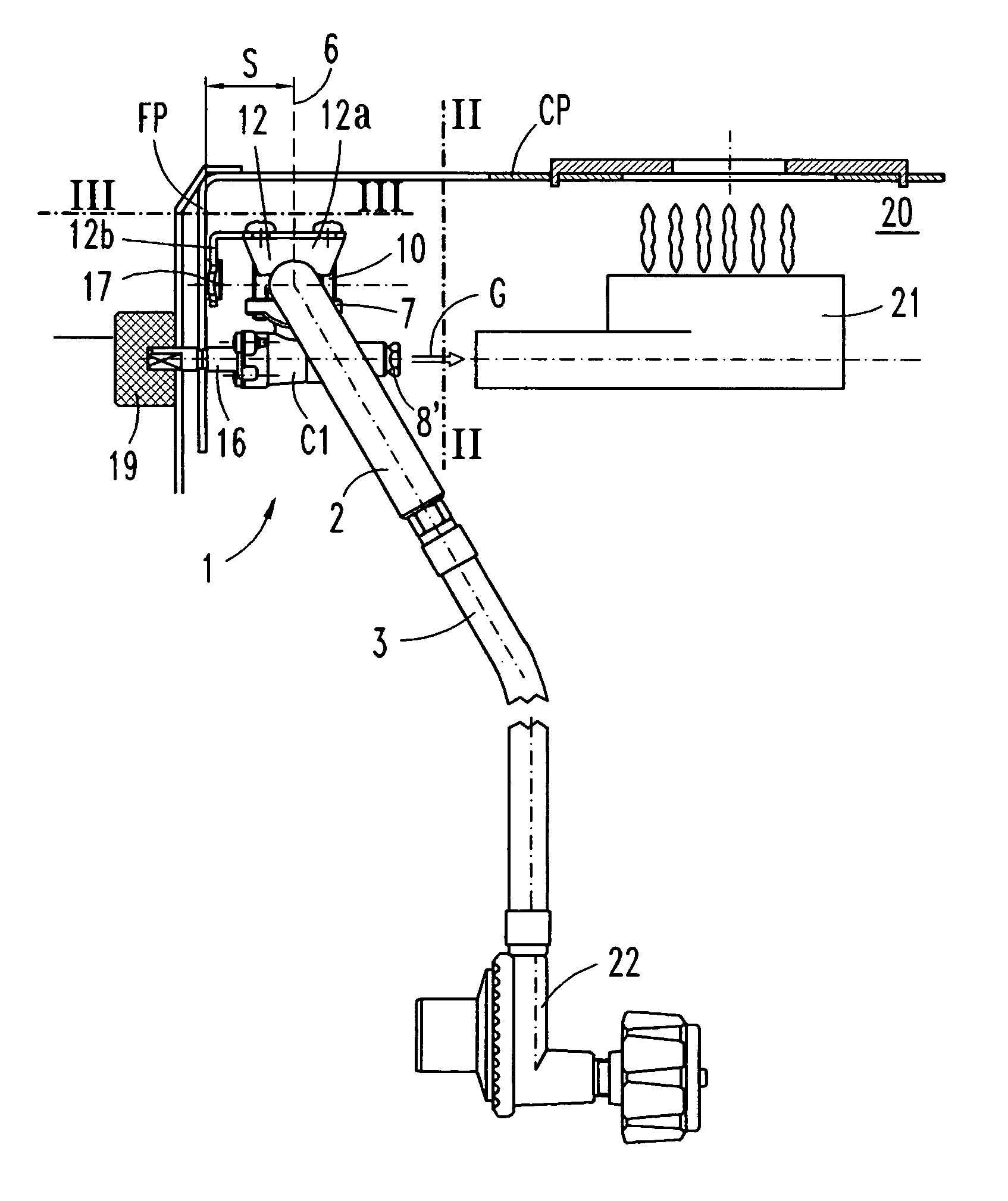
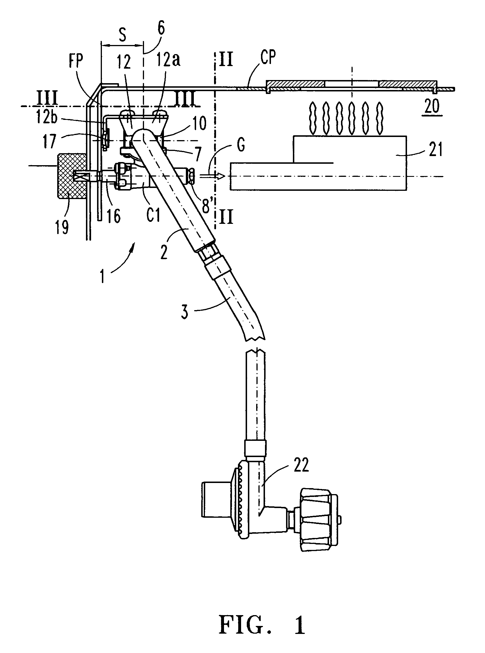
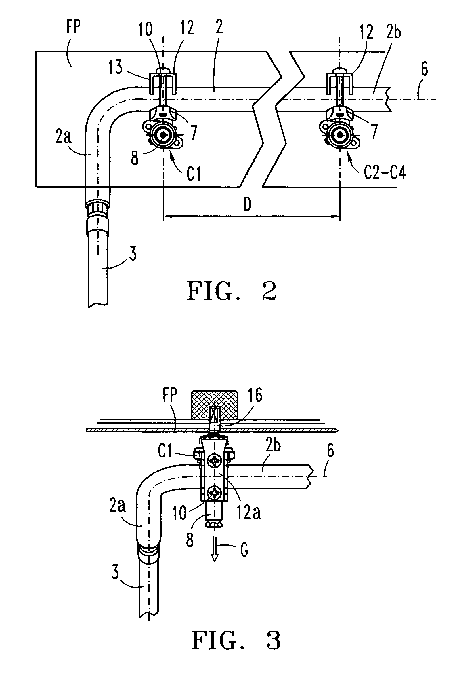
[0012]In reference to FIGS. 1-4, the gas manifold assembly according to one embodiment of the invention is installed on a cooking appliance 20 with top burners 21 forming a working plane CP. The manifold assembly comprises an elongated manifold conduit 2 of a straight preferably cylindrical configuration, a feed pipe 3 connected to one end of the manifold conduit, two or more rotary taps C1-C4, four instance four taps mounted in line on the manifold conduit 2 and various squared mounting device 12, each one for either one of the taps C1-C4, which are used also as a means for installing the manifold assembly 1 on the front panel FP of the cooking appliance 20.

[0013]The gas manifold conduit 2 has a straight part running parallel to the front panel FP of the appliance, on which there are four taps C1-C4 disposed and a bent part extending towards the inside of the appliance, at the end of which the flexible feed hose is connected from a gas supply regulator 22.

[0014]Taps C1-C4 have an a...


PUM


Abstract

The gas manifold assembly (1) is adapted to a cooking appliance for supplying the burners (21) thereof, and is equipped with various taps (C1-C4) of the rotary type, installed on a elongated tubular-shaped manifold conduit (2), which is disposed parallel to the front wall (FP) of the appliance and supported on it. The taps (C1-C4) have a respective installation seat (7) with a built-in gas intake connected to the elongated conduit (2), and mounting is carried out by means of a one-piece mounting device (12), which in turn has an integral means (12b) for supporting and fastening the manifold assembly (1) to the front wall (FP), for which purpose the aligned tap drive shafts (16) stand proud of the front wall (FP) and the tap outlet conduits (8) face and adjoin their respective burner (21).

Description

TECHNICAL FIELD OF THE INVENTION[0001]The present description relates not only to the supply of gas to a domestic cooking appliance provided with a number of top burners by way of a gas flow manifold assembly with a number of regulating taps of the rotary type installed on a manifold conduit, but also to the manifold assembly installation means.PRIOR ART[0002]Fuel gas manifold assemblies for a cooking appliance fitted with various rotary type taps are already known. The manifold assembly is installed on a front panel of the cooking appliance, with the aligned tap drive shafts placed so that they stand out from the front panel of the appliance. The taps are installed on a gas rail or manifold conduit by means of a tightening clamp with screws.[0003]The gas manifold assembly disclosed for example in GB-2182429-A comprises a main manifold conduit or cylindrical section common rail on which various rotary manual taps are installed in line. The tap drive shafts extend in alignment by way...

Claims


Application Information

Patent Timeline
Patent Type & Authority Patents(United States)
IPC IPC(8): F24C3/00F24C3/12
CPCF24C3/12Y10T137/6123
Inventor ALBIZURI, INIGO
Owner COPRECITEC
Why Eureka
Try Eureka