Sulky for self-propelled machines

a self-propelled machine and sulky technology, which is applied in the direction of trailer steering, transportation and packaging, tractors, etc., can solve the problems of rider likely to topple as the sulky suddenly pitches toward the ground, dislodgment of the operator or overturning the entire sulky, and achieve the effect of stabilizing the sulky

Inactive Publication Date: 2007-11-27
OMSTEAD MICHAEL J
View PDF36 Cites 25 Cited by
  • Summary
  • Abstract
  • Description
  • Claims
  • Application Information

AI Technical Summary

Benefits of technology

[0009]The connector of the invention is zero-weight bearing or “floating.” In other words, the wheels of the sulky are disposed in such a way that the weight of a rider and/or load is distributed among the wheels rather than on the connector. This provides a stability advantage over one and two wheeled sulkies.
[0010]Moreover, in one particularly preferred embodiment of the invention, the sulky includes a platform having a top and a bottom, a pair of wheels disposed upon an axle proximal to the

Problems solved by technology

Such wheel configurations can be unstable because substantial weight (including that of the rider) is inherently placed upon the structure that connects the sulky to the self-propelled machine.
Thus, if the connection between the sulky and pulling machine undergoes stress (e.g., difficult topography) or fails outright, the r

Method used


Image

  • Sulky for self-propelled machines
  • Sulky for self-propelled machines
  • Sulky for self-propelled machines

Examples


first embodiment

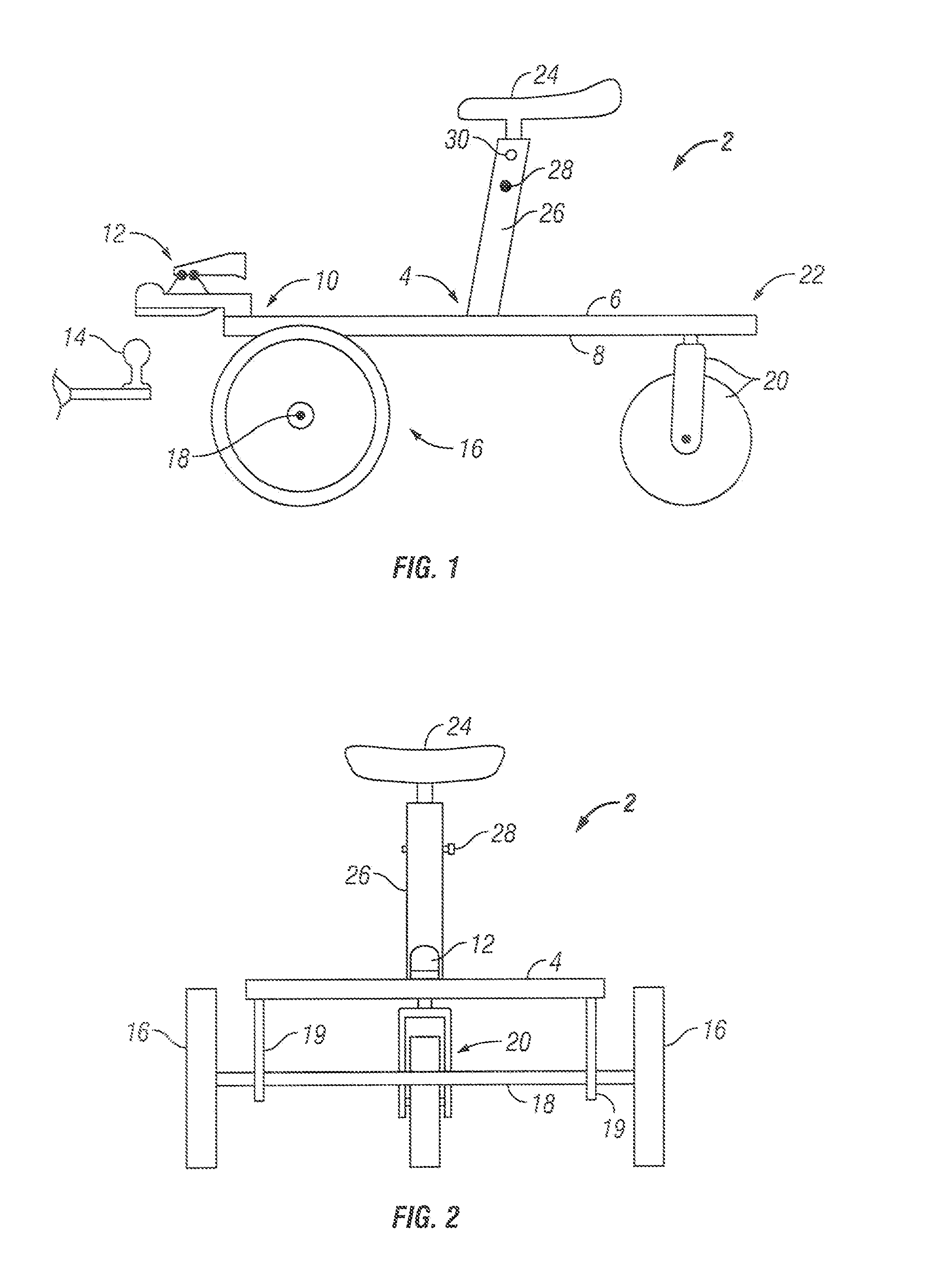
[0020]Turning to the figures, wherein like number designate like elements, FIGS. 1 and 2 illustrate the invention. The sulky 2 includes a platform 4 having a top 6 and a bottom 8. Disposed upon the front 10 of the platform 4 is a connector 12. The connector 12 is adapted to engage a second connector 14 on a self-propelled apparatus (as shown, for example, in FIG. 5). Of course, “front,”“rear,”“top,” and “bottom” are relative terms and, as such, are illustrative and not meant to limit the location of an element to a single position on the platform.

[0021]At least three wheels are disposed upon the bottom 8 of the platform 4 in an arrangement such that said connector 12 is zero-weight bearing. Preferably, a pair of wheels 16 are disposed upon an axle 18 that is rotatably mounted on a pair of brackets 19 located proximal to the front 10 of platform 4, while a single caster 20 is centrally disposed proximal to the rear 22 of the platform. A seat 24 is attached to a post 26 on the top 6 o...

second embodiment

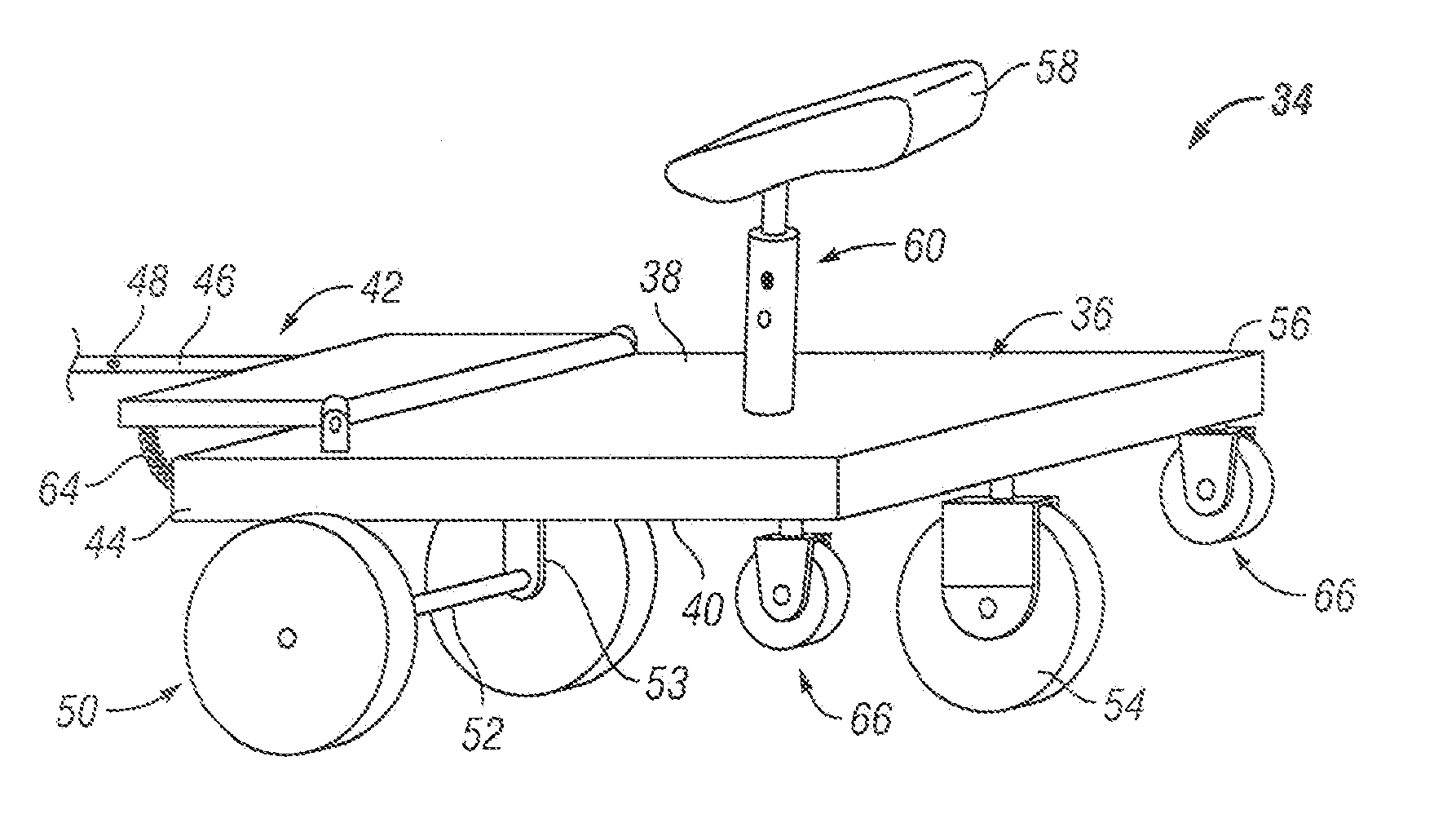
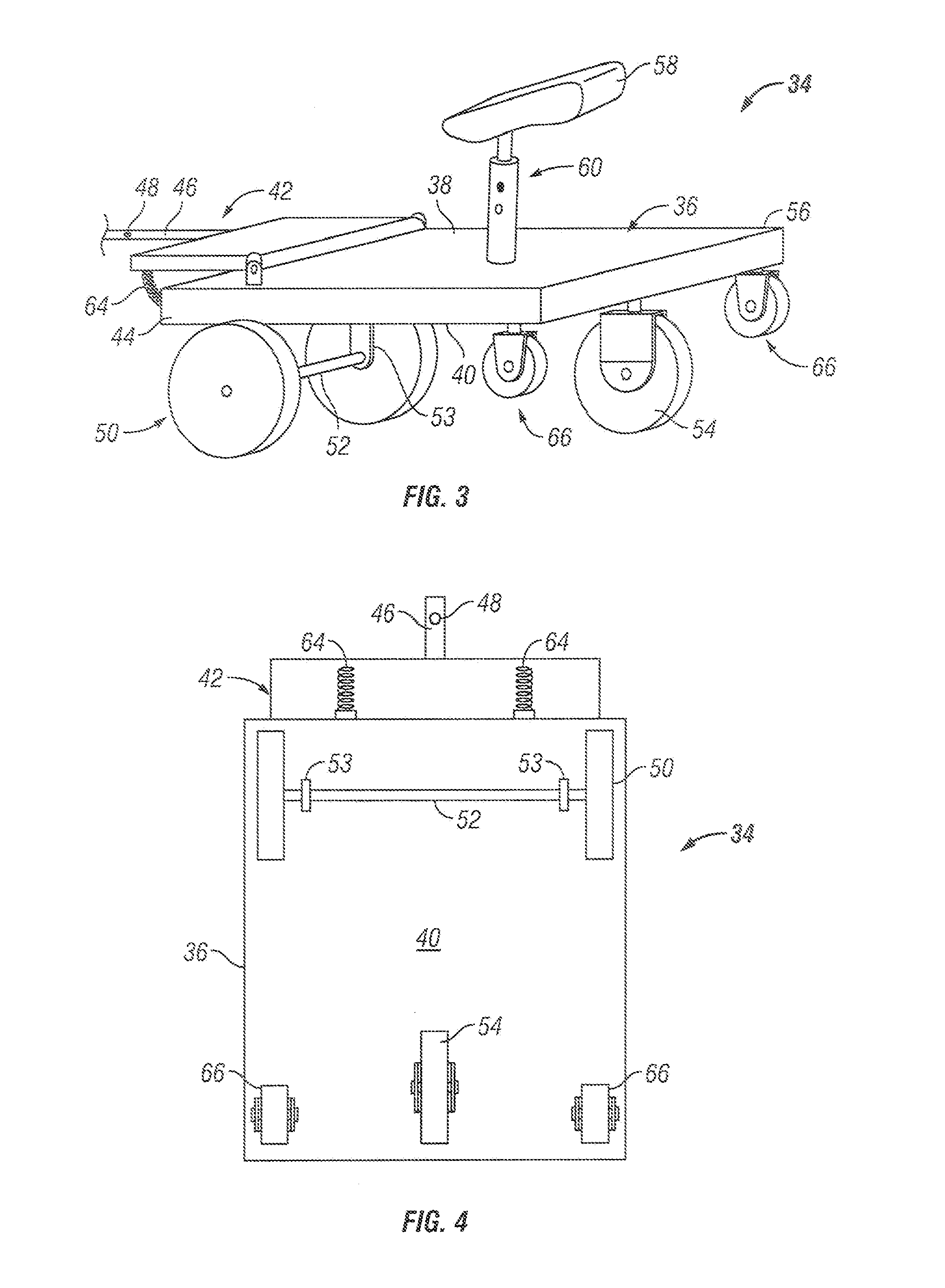
[0022]As shown in perspective view in FIG. 3, the invention features a sulky 34 that includes a platform 36 having a top 38, a bottom 40, and a platform extension 42 hingedly mounted at 43 proximal to the platform front 44. A connector 46 having an opening 48 (for receiving a lock pin) is attached to the platform extension 42 to engage a second connector on a self-propelled machine.

[0023]Three wheels are disposed upon the bottom of the platform in an arrangement such that said connector is zero-weight bearing. Thus, the wheel arrangement of this embodiment includes a pair of wheels 50 disposed upon an axle 52 rotatably mounted through brackets 53, which are attached proximal to the front 44 of the platform bottom 40, and one wheel 54 disposed proximal to the rear 56 of platform bottom 40. In this case, the one wheel 54 is a castor. However, other types of wheels may be used. A seat 58 is adjustably mounted on a post 60 on the top 38 of platform 36 from which a rider controls the sel...


PUM


Abstract

A sulky that includes a platform having a top and a bottom, a connector disposed upon a front of the platform, at least three wheels disposed upon the bottom of the platform in a wheel arrangement such that the connector is zero-weight bearing, and a seat disposed upon the top of the platform. A hinged platform extension provides added stability.

Description

BACKGROUND OF THE INVENTION[0001]1. Field of the Invention[0002]This invention relates generally to apparatuses used in conjunction with self-propelled machines, and, more particularly, to sulky-like carts that attach to outdoor equipment such as landscaping machines.[0003]2. Description of the Related Art[0004]Devices for attachment to self-propelled machines, such as power lawn mowers, provide a means for allowing a user to ride along with the machine. Such devices have been in use for many years and are commonly referred to as a “sulky.” A sulky typically includes a platform mounted between two wheels that is connected to the self-propelled machine by a tow bar.[0005]For example, a sulky apparatus is illustrated in U.S. Pat. No. 5,004,251 to Velke that employs a platform covering a single wheel located between the foot plates for the operator's feet. The platform is pivotally connected to one end of the tow bar along a vertical axis, allowing free rotation of the platform horizon...

Claims


Application Information

Patent Timeline
IPC IPC(8): B62D63/00
CPCA01D67/00B62D49/0671B62D63/06B62D59/02B62D51/04
Inventor OMSTEAD, MICHAEL J.
Owner OMSTEAD MICHAEL J
Why Eureka
Try Eureka